Preparing for the 139th Canton Fair in April 2026

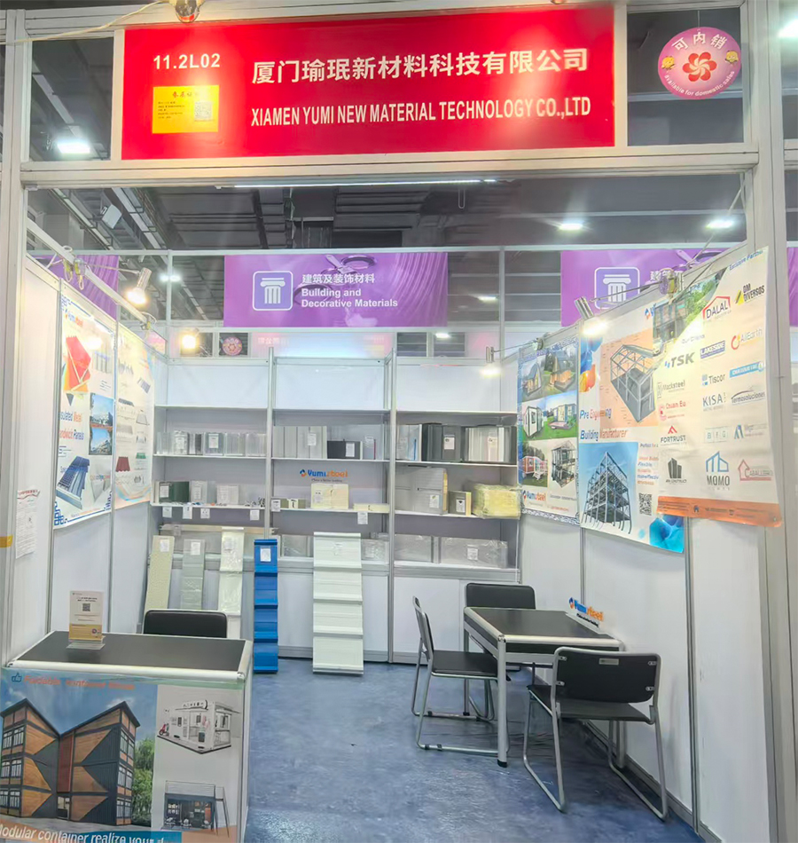
Yumisteel entered the 139th Canton Fair in April 2026 with thorough preparation and high expectations. As one of the most influential trade events in the global construction industry, the Canton Fair attracts thousands of buyers from all over the world. Knowing this, Yumisteel invested weeks in booth design, product displays, and technical documentation to ensure a professional and welcoming presentation. The team prepared samples of sandwich panels, color steel tiles, decking sheets, container houses, and full steel structure building models. Marketing materials were translated into multiple languages to better serve international visitors. Every team member was trained to answer technical questions on the spot. With a clean, organized booth and a clear focus on quality and customization, Yumisteel was ready to meet the world.

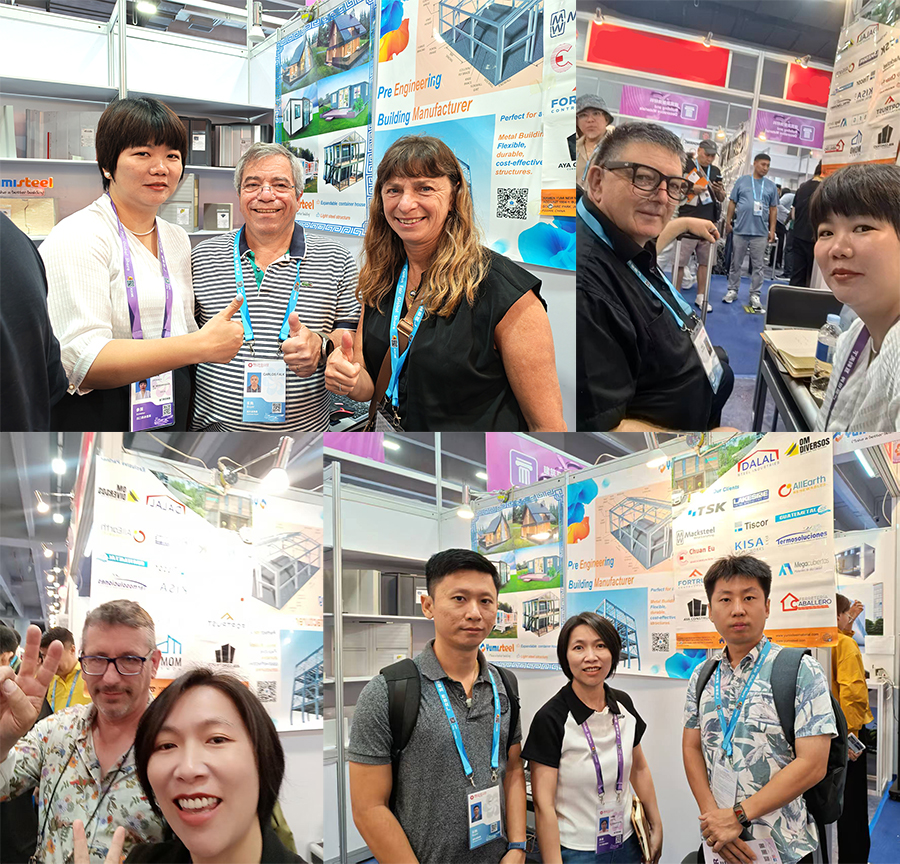
Yumisteel booth in Canton Fair

Five Days of Non-Stop Visitor Traffic – April 23 to 27, 2026

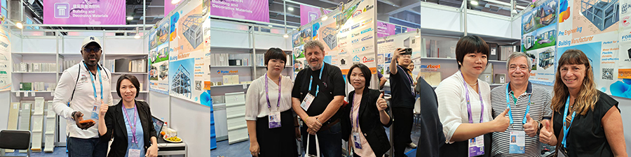
From April 23 to April 27, 2026, the Yumisteel booth welcomed a steady stream of visitors every single day. The five-day was intense but rewarding, with barely a quiet moment. Buyers from Europe, the Middle East, Southeast Asia, Africa, and South America stopped by to examine product samples, ask about pricing, and discuss project requirements. Many visitors arrived with specific construction needs and stayed for in-depth conversations. The Yumisteel team found themselves constantly moving between explaining technical specifications, handing out brochures, and scheduling follow-up meetings. By the end of each day, the inquiry log was full, and the team was exhausted but excited. The level of interest was beyond expectations, confirming that global demand for prefabricated building solutions continues to grow fast.

Group photo at the Canton Fair

Steel Structure Buildings Drew the Most Inquiries

Yumisteel offers a wide range of products, including sandwich panels, color steel roofing sheets, floor decking, container houses, and complete steel structure buildings. However, during this Canton Fair, steel structure buildings received the highest number of serious inquiries. Buyers were especially interested in using steel buildings for self-built homes, warehouses, and office spaces. Many visitors asked about light steel frame systems that are easy to transport, quick to assemble, and strong enough to withstand local weather conditions. Some customers brought rough drawings of their land and asked for customized designs. Others wanted to know about insulation options, foundation requirements, and delivery times. It became very clear that steel structure buildings have moved from a niche product to a mainstream choice for individual homeowners and small business owners alike.

Group photo at the Canton Fair

After the Fair – Yumisteel's Team Steps In to Deliver Solutions

Once the Canton Fair ended, the real work began for the Yumisteel business team. Every inquiry collected during those five days was carefully reviewed and sorted. The team now focuses on providing the best possible solutions to each customer based on their specific needs — whether it is a small self-built home in a rural area, a mid-sized warehouse near a city, or a modern office space on a tight schedule. Yumisteel's engineers work closely with clients to adjust designs, select the right materials, plan logistics, and offer installation guidance. No two projects are exactly the same, and the team takes pride in solving real-world problems with practical, affordable, and durable steel structure buildings. For anyone who visited the Yumisteel booth at Canton Fair 2026, a professional and caring response is already on its way.

For more information needed or any inquiry,please feel free to contact Yumisteel team.

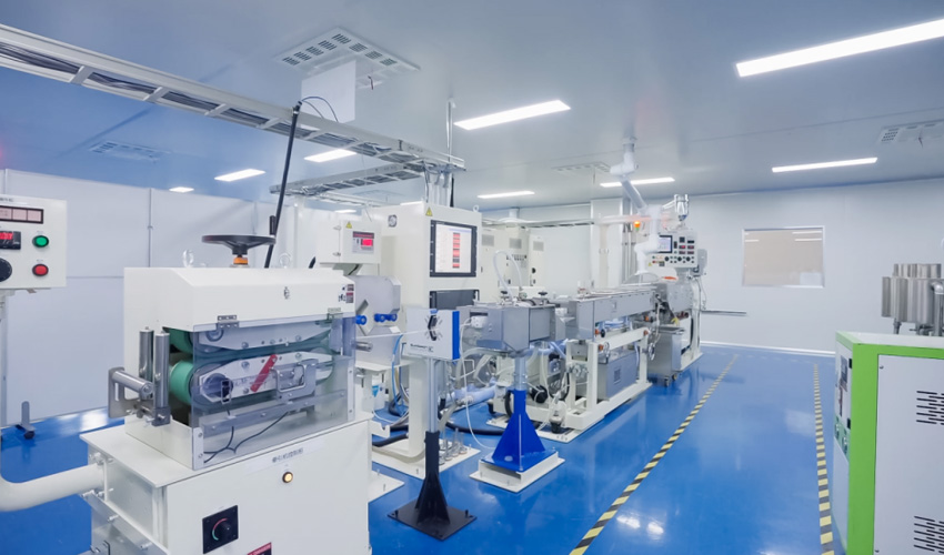
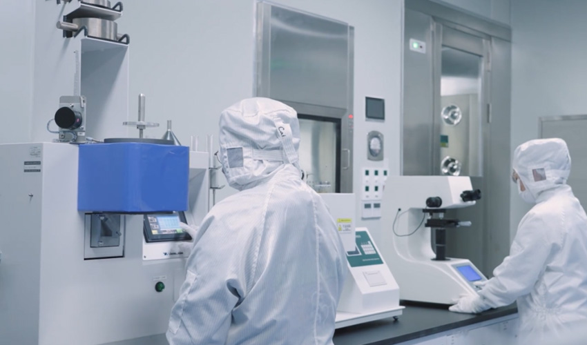
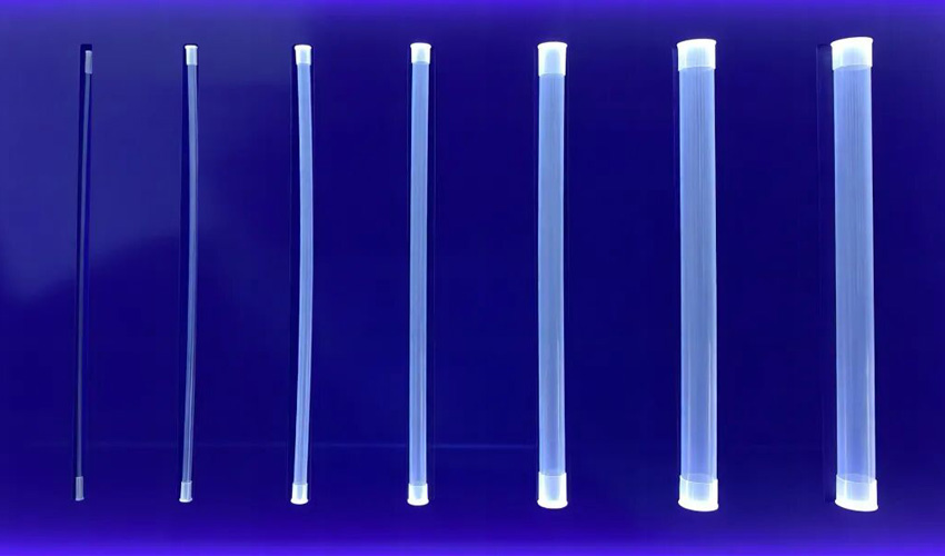
Boasting excellent chemical inertness, ultra-low metal ion leaching, superior inner wall smoothness and outstanding stability over a wide temperature range, Ultra-Clean PFA Tube serves as an essential core pipeline component for semiconductor photoresist transfer systems.


ultra-clean PFA Tube


As chip manufacturing processes evolve toward more advanced nodes, fabrication fabs have raised stricter standards for the purity and particle control of photoresist delivery pipelines. As a vital fluid passage connecting storage tanks, pumps, valves and other components, Ultra-Clean PFA Tube must withstand long-term corrosion from strong organic solvents in photoresists. Meanwhile, it is required to deliver ultra-low metal ion leaching and superior particle control performance, so as to minimize photoresist contamination and ensure the yield of products manufactured by advanced processes.

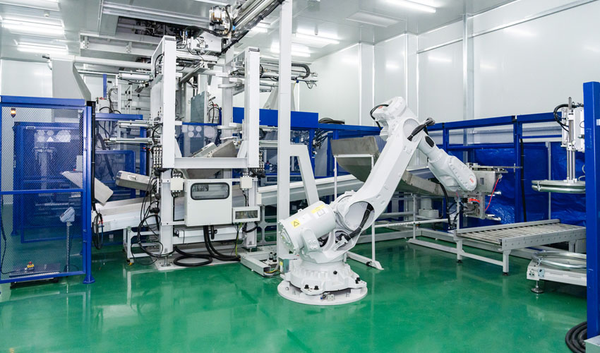
For a long time, the domestic market for semiconductor-grade Ultra-Clean PFA Tube has been highly dependent on imports. Particularly for the production of advanced logic and memory chips, high-end products are still dominated by a small number of international manufacturers. Faced with technical bottlenecks in core fluid pipeline materials for semiconductors, BSL has continuously made breakthroughs in key processes including precision extrusion molding of high-purity PFA, steadily improved the control capability of metal leaching, and upgraded full-process clean manufacturing technologies. In addition, BSL is accelerating product verification and on-site application at mainstream fabs and semiconductor equipment suppliers. Our product portfolio features high batch consistency, superior chemical resistance and ultra-high purity, fully meeting the rigorous requirements of photoresist transfer systems for advanced processes. It provides solid support for the independent controllability and sustainable development of key semiconductor consumables.

01 Chemical Resistance


BSL adopts high-purity PFA raw materials. Innovative processes improve the density and uniform molecular structure of the tubes, reduce micropores and weld defects, and effectively block penetration channels for corrosive media, which greatly enhances the overall corrosion resistance and anti-swelling performance. When in long-term contact with common organic solvents for photoresists (such as PGMEA and Cyclohexanone), as well as chemicals widely used in semiconductor wet processes including sulfuric acid and hydrofluoric acid, the tubes show no swelling, cracking or mass loss, delivering excellent chemical resistance.

Test results show that after 168 hours of immersion in 37% hydrochloric acid at 85℃, BSL Ultra-Clean PFA Tube has no obvious changes in appearance and dimensions, and the total leachables remain stable. Its overall chemical resistance has reached the world’s advanced level.

02 Low Metal Ion Leaching


Manufactured with high-precision production equipment, BSL Ultra-Clean PFA Tube maintains ultra-high purity. In compliance with the Group Standard for Semiconductor-Grade Perfluoroalkoxy (PFA) Tubes (hereinafter referred to as the Standard), the leaching levels of metal ions such as aluminum, calcium, chromium, iron and sodium are all controlled below the limits specified in the Standard. Especially for critical impurities including sodium, iron and calcium, our product delivers performance equivalent to or even better than international competing products, ensuring fluid purity from pipelines to wafers throughout the whole process.

03 Low TOC and Particulate Leaching

The tubes undergo ultrasonic cleaning and multi-stage ultrapure water flushing, which drastically reduces organic residues and loose particulates on the inner wall. The Standard stipulates that the total organic carbon (TOC) content shall not exceed 2000 μg/m², while the actual measured TOC value of BSL products is controlled within 60% of the standard limit.

In addition, particulate leaching fully complies with SEMI Standards. In particle-sensitive photolithography processes such as photoresist coating and development, particle detachment from the tube inner wall is kept to a minimum, avoiding wafer surface scratches and short-circuit defects.

04 Smooth Inner Surface

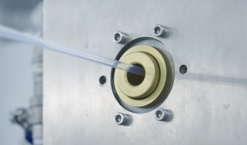
Adopting high-precision extrusion dies and stable process parameters, the average surface roughness (Ra) of the tube inner wall of BSL products is steadily controlled at ≤0.25 μm. Atomic Force Microscope (AFM) tests verify that the inner wall is smooth and free of microcracks. This effectively suppresses fluid turbulence and reduces particle adhesion and chemical residue accumulation.

Independently developed BSL Ultra-Clean PFA series products fully satisfy the extreme demands of advanced semiconductor processes for photoresist transfer. They are applicable to harsh working scenarios requiring high cleanliness, strong corrosion resistance and high precision, ensuring stable operation of fluid transfer systems and protecting manufacturing yield.


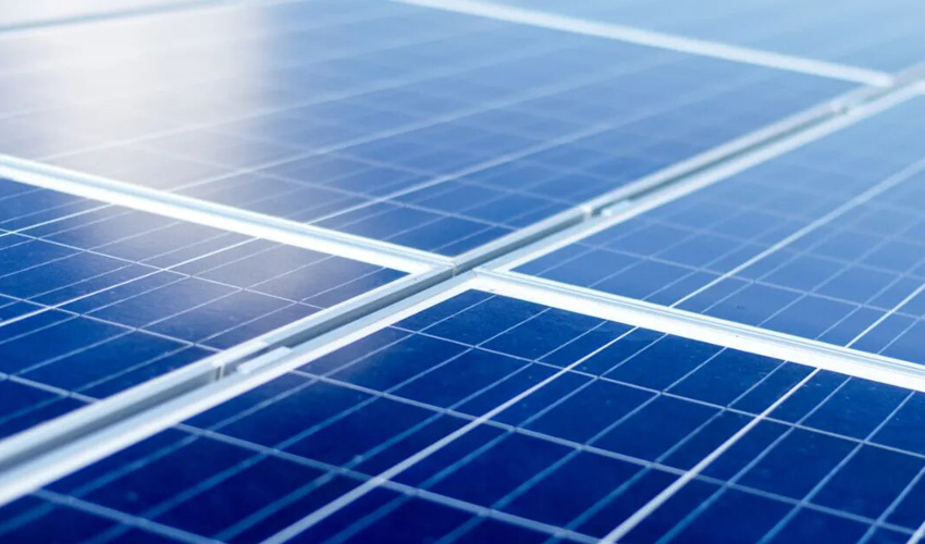
In the photovoltaic industry, the production and maintenance of solar panels and modules impose extremely high requirements on cleanliness. Studies have shown that dust accumulation can reduce the efficiency of solar panels, and power loss can be substantial under scenarios with heavy dust coverage. Therefore, implementing strict cleanliness control in production, assembly and daily operation & maintenance has become an industry consensus for photovoltaic enterprises.


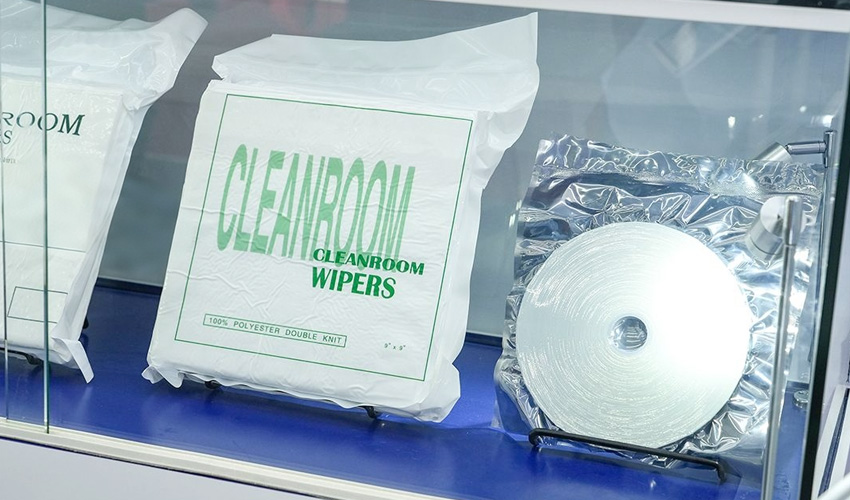
With superior properties including low lint generation, high wiping efficiency, strong adsorption capacity, anti-static performance and soft surface texture, BSL (Baoshili) Cleanroom Wiper has evolved into an indispensable cleaning consumable in the photovoltaic industry.

01 Precision Cleaning of Module Surfaces

During the manufacturing and subsequent power inspection of solar panels, their surfaces are highly prone to deposited dust and processing oil residues. Wiping with professional low-ion-release Cleanroom Wiper can efficiently remove contaminants while avoiding micro-scratches on the surface, ensuring the light absorption efficiency of modules remains intact.

02 Internal Maintenance of Production Equipment

In high-precision processes such as screen printing and laser cutting, free particles attached to the interior of equipment and fixture surfaces may easily mix into solar cells, causing appearance defects or performance failure. Regular cleaning of key contact surfaces of production equipment with Cleanroom Wiper is crucial to stabilizing the yield rate of continuous production.

03 Emergency Handling of Liquid Contaminants

Photovoltaic production lines often encounter accidental splashes of cleaning solutions, bonding additives and organic solvents. Improper disposal will contaminate adjacent workstations. Featuring a microfiber structure, Cleanroom Wiper boasts far stronger liquid adsorption capacity than ordinary cotton cloth. It can quickly remove residual liquids spilled accidentally during production, reducing secondary risks caused by chemical diffusion.

04 Prevention of Static Damage Risks

Given that photovoltaic module packaging and lamination processes are vulnerable to electrostatic impact, anti-static Cleanroom Wiper is required to timely dissipate static charges generated by operational friction. This prevents static electricity from breaking down precision power generation structures, damaging cell grid lines or transparent conductive films, and improves electrical safety in precision operations.

05 Daily Maintenance Support

From pre-cleaning before lamination and glue overflow treatment after lamination, to wiping optical lenses of testing equipment and maintaining laboratory countertops, the high wiping efficiency of Cleanroom Wiper fully meets daily cleaning and maintenance needs.

Core Advantages of BSL Cleanroom Wiper

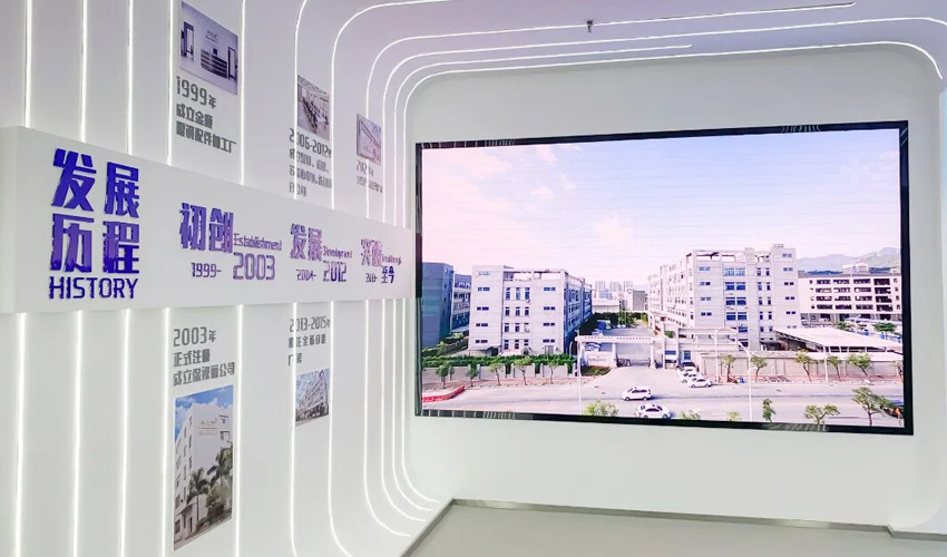
BSL Cleanroom Wiper is available in multiple material specifications and models, including microfiber and 100% polyester fiber variants. It meets high industry standards in core indicators such as particle release, lint shedding and ion residue. Founded in 1999, the company has accumulated advanced technological craftsmanship over decades, endowing BSL Cleanroom Wiper with outstanding performance across multiple dimensions.


Cleanroom Wipes


Low Lint Generation

Adopting continuous knitting technology as well as laser and ultrasonic edge sealing, BSL Cleanroom Wiper effectively avoids scratches on photovoltaic glass and backsheets caused by loose threads from traditional hot cutting.

High Adsorption Capacity

The microfiber structure endows the material with powerful capillary wicking effect, delivering excellent instant capture and locking performance against dust, processing oil stains, residual glue and additive liquids.

Anti-Static Design

Optional anti-static wiping variants effectively inhibit static charge accumulation and eliminate potential impacts of point discharge on sensitive photovoltaic modules and precision manufacturing environments.

Soft and Damage-Free Surface

The Cleanroom Wiper features a soft and smooth surface, causing no micro-marks or damage even when repeatedly wiping high-transmittance coated photovoltaic glass.

Wet and Dry Dual-Purpose

Whether for dry dust removal before sampling inspection or precision wet wiping with solvents such as isopropyl alcohol, BSL Cleanroom Wiper maintains stable material strength and cleaning efficiency under various working conditions.


As the photovoltaic industry raises higher requirements for process yield and module service life, high-quality cleanroom consumables have become a key factor for differentiated competition. Drawing on over two decades of large-scale production capacity in cleanroom wiper materials, BSL continues to provide stable and reliable Cleanroom Wiper Solutions for solar cell factories and end-user operation & maintenance service providers.


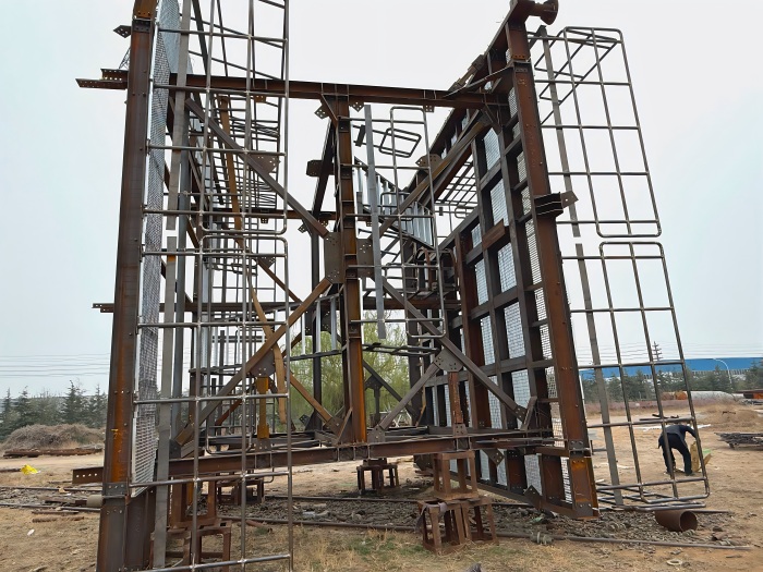
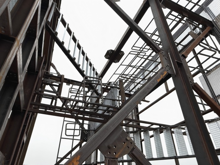
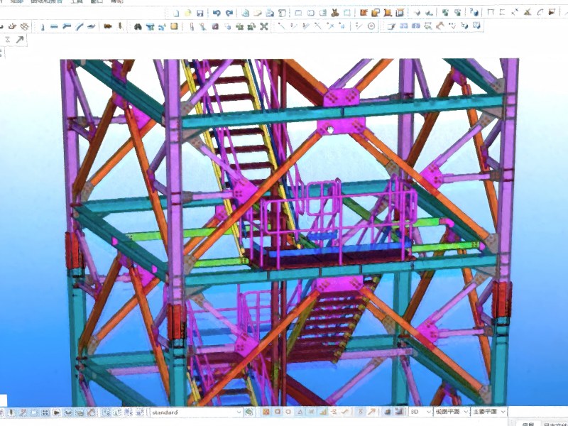
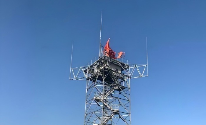
In the world of critical radar infrastructure, precision is everything. Modern radar systems—whether for meteorological monitoring, air traffic control, or defense—demand an exceptionally stable platform. Even minute structural vibrations or sway in a radar tower can introduce phase errors, distort beam patterns, and degrade data quality【7+L9-L12】. Yet these same towers must also be accessible. Technicians need to climb them regularly for calibration, antenna maintenance, and emergency repairs. The challenge is to integrate safe climbing systems and equipment platforms into the tower's structural envelope without compromising the stiffness that radar precision demands.

radar support tower

The Tension Between Access and Stiffness

Radar support structures are governed by stringent dynamic requirements. A tower's natural frequency must be kept sufficiently high, and well separated from forcing frequencies generated by the rotating antenna and environmental wind loads, to avoid resonant coupling that would smear radar images. Every added component—a ladder rung, a platform support bracket, a cable guide—alters the structure's mass and stiffness distribution. Poorly designed access features can introduce local flexibility or add mass in locations that lower critical natural frequencies.

A radar tower is engineered not just to carry weight, but to resist deformation under dynamic loads with exceptional rigidity. The natural frequency is a function of stiffness and mass. For heavy radar antennas and radomes, reducing mass is often impractical, so the primary lever is to maximize structural stiffness. Access features must therefore be embedded into the tower's primary structural logic rather than treated as afterthoughts.


radar support tower


Regulatory Framework for Safe Access

Radar towers must comply with safety standards that are evolving toward more effective fall protection. The ANSI/ASSE A10.48 standard provides comprehensive safety guidance for communication structures, including antenna and antenna-supporting structures, covering fall protection and rescue, climbing facilities, and training. The 2023 revision of this standard, effective January 1, updated safety practices for construction, demolition, modification, and maintenance.

OSHA regulations require 100% fall protection for personnel working at heights above 6 feet. For fixed ladders over 24 feet, the regulatory trend has shifted decisively: ladder cages are being phased out, with a 2036 deadline for their replacement on new installations and major modifications. Cages do not arrest vertical falls and complicate rescue, making modern cable- or rail-based systems the preferred solution.


Choosing the Right Climbing System

For radar towers, not all climbing safety solutions are equal. Vertical cable and rail systems have become the industry standard because they provide continuous attachment without requiring the user to disconnect at intermediate points. Tractel's FABA™ fall arrest systems allow for safe climbing on fixed vertical ladders at any height on towers, masts, and pylons. The stopcable® system features a detachable fall arrester with built-in energy absorber that locks instantly on the cable upon a fall, minimizing free-fall distance. MSA Safety's Latchways® systems (LadderLatch and TowerLatch) incorporate a patented starwheel component that enables smooth movement through cable guides without pulling cable out of the guides.


System Type Fall Protection Mechanism Suitability for Radar Towers
Fixed Ladder (No Protection) None—relies on 3-point contact Not acceptable—fails regulatory compliance
Ladder with Cage Physical barrier prevents sideways falls Phased out—does not arrest vertical falls; complicates rescue
Vertical Cable/Rail System Harness-mounted fall arrester slides on cable/rail Recommended—arrests falls within inches; hands-free climbing; minimal stiffness impact
Personal Fall Arrest System (PFAS) Harness + lanyard attached to anchor point Supplemental—suitable for platform work but not as primary climbing system

radar support tower


Equipment Platforms: Stiffening Rather Than Compromising

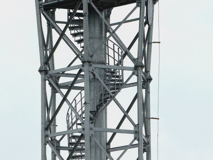
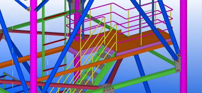
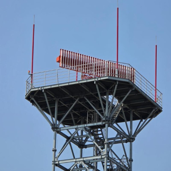
Radar towers typically feature multiple platforms: a lower platform for equipment access and an upper platform at the radome level for antenna installation. These platforms serve as maintenance work areas and provide mounting points for ancillary equipment. From a structural perspective, they should be integrated as stiffened diaphragms—their floor beams and bracing must contribute positively to the tower's overall rigidity.

Key design principles for platforms in radar applications:

  1. · Full-perimeter bracing: Platforms should be tied into all tower faces with cross-bracing or stiffened decking to act as horizontal stiffening rings. This prevents local mode shapes that could otherwise reduce natural frequencies.

  2. · Load transfer: Platform loads must be transferred into tower legs via dedicated connection nodes, not through diagonal bracing alone. This ensures predictable force paths and avoids unintended stress concentrations.

  3. · Open steel grating: Preferred over solid plate because it reduces wind load accumulation, improves visual inspection of members below, and sheds ice more readily. The open design also minimizes added mass, supporting the goal of maximizing stiffness-to-weight ratio.

Advanced bracing patterns—such as K-bracing or X-bracing—are analyzed and optimized to ensure a stiff, robust platform that minimizes deflection under operational loads. Platforms also serve as rescue staging areas—required resting points on tall ladders, typically every 9 to 12 metres—where a worker can rest or await assistance.


radar support tower


Lightning Protection Integration

Radar towers are often sited in exposed locations, making lightning protection a critical consideration. The tower's climbing systems and platforms must be integrated with the external lightning protection scheme. According to ITU-T K.112, a radio base station's lightning protection system includes air-termination, down-conductors, earthing network, bonding conductors, and surge protective devices. All metallic access components—ladders, platform railings, cable guides—must be bonded to the grounding system to prevent dangerous side-flashes. The steel tower itself serves as the primary down-conductor, but grounding continuity must be verified for all attached access hardware. The rebar in concrete tower foundations should be used to augment the grounding system, coupling strike energy through conductive concrete.


radar support tower


Conclusion

Access systems in radar towers are not peripheral add-ons—they are integral to the structure's ability to be maintained, calibrated, and ultimately to perform its precision mission. When properly integrated, safe climbing systems and equipment platforms enable the tower to be both accessible and accurate. Vertical cable fall-arrest systems provide continuous protection without compromising stiffness. Platforms designed as stiffened diaphragms contribute positively to the tower's dynamic performance. And comprehensive lightning protection ensures the safety of personnel during climbs in exposed conditions. For structures where a fraction of a degree of antenna deflection can render radar data unreliable, this integration is not optional—it is fundamental.


Ready to integrate safe, radar‑grade access systems into your next tower project? Contact our engineering team today for custom design support and a detailed quote.


Contact Us

Radar towers serve a uniquely demanding purpose. Unlike communication towers that simply hoist passive antennas, radar towers must provide an exceptionally stable platform for rotating, precision‑sensing equipment. A slight structural deflection, an unexpected vibration mode, or—just as critically—an access component that introduces unwanted flexibility can compromise the radar's pointing accuracy and data fidelity.


radar support tower


Yet these towers must also be accessible. Technicians need to climb them for routine calibration, antenna maintenance, and emergency repairs. The challenge is to integrate safe climbing systems and equipment platforms into the tower's structural envelope without sacrificing the stiffness that radar precision demands.


The Tension Between Access and Stiffness

Radar support structures are governed by stringent dynamic requirements. A tower's natural frequency must be kept sufficiently high, and well separated from the forcing frequencies generated by the rotating antenna and environmental wind loads, to avoid resonant coupling that would smear radar images. Every added component—a ladder rung, a platform support bracket, a cable guide—alters the structure's mass and stiffness distribution. Poorly designed access features can introduce local flexibility, create stress concentrations, or add mass in locations that lower critical natural frequencies. The objective, therefore, is to embed safety and access features into the tower's primary structural logic rather than treating them as afterthoughts.


Regulatory Framework for Safe Access

Radar towers, like communication towers, must comply with an evolving suite of safety standards. In North America, the ANSI/ASSE A10.48‑2016 Standard establishes comprehensive criteria for safe work practices on communication structures, covering everything from fall protection to climbing facilities. This standard has become the benchmark for the industry. Meanwhile, OSHA regulations require 100% fall protection for employees exposed to elevations above 6 feet while working on towers. For fixed ladders over 24 feet, OSHA historically permitted ladder cages, but the regulatory trend has shifted decisively: cages are being phased out, with a 2036 deadline for replacement. Modern systems rely on vertical lifelines or rigid rail fall‑arrest systems, which are more effective at actually stopping a fall.


Internationally, EN 353‑1:2014+A1:2017 governs guided type fall arresters on rigid anchor lines, while ANSI Z359.16‑2016 covers safety systems for climbing fixed ladders. Products compliant with these standards, such as the stopcable system, feature detachable fall arresters with built‑in energy absorbers that lock instantly upon a fall and minimise free‑fall distance.


radar lattice tower


Choosing the Right Climbing System: A Comparative Overview

For radar towers, not all climbing safety solutions are equal. The table below compares the main options:


System Fall Protection Mechanism Key Features Suitability for Radar Towers
Fixed Ladder (No Protection) None—user relies on 3‑point contact Lowest cost, simplest installation Not acceptable—fails regulatory compliance and presents extreme risk
Ladder with Cage Physical barrier prevents falling sideways/backward Simpler for untrained users; cages do not arrest vertical falls Phased out—offers false security and complicates rescue; not recommended for new builds
Vertical Cable/Rail Safety System Harness‑mounted fall arrester slides along permanently installed cable Arrests falls within inches; allows free climbing with both hands; can be retrofitted Recommended—meets ANSI/OSHA requirements; minimal impact on tower stiffness; supports up to 4 users on one system
Personal Fall Arrest System (PFAS) Harness + lanyard attached to independent anchor point Highly effective but relies on correct user action and anchor availability Supplemental—suitable for platform work, but not as primary climbing system due to repeated connect/disconnect requirements

Key selection insights:

  1. Vertical cable systems (e.g., Latchways® TowerLatch or Tractel stopcable®) are increasingly the industry standard because they provide continuous attachment and do not require the user to disconnect at intermediate guides. The patented starwheel component enables smooth movement through cable guides without pulling cable out of the guides, a critical feature when climbing past multiple platform levels.

  2. For monopole radar towers, dedicated universal mounts are available (e.g., Universal Monopole Mount Safe Climb Systems), using 3/8″ galvanised wire rope with cable stand‑offs every 25 feet and a sealed anchor head with impact attenuator.

  3. Ladder cages should be avoided on new radar towers: they do not prevent vertical falls and can make rescue more difficult.


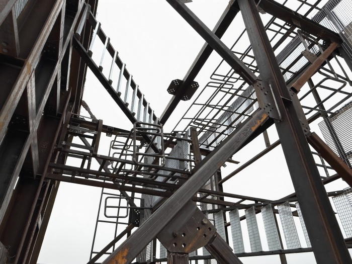
radar lattice support tower


Equipment Platforms: Access Without Compromising Stiffness

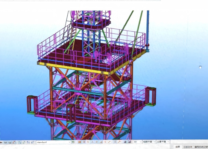
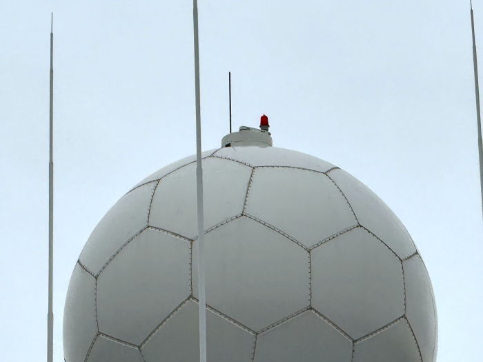
Radar towers typically feature multiple platforms: a lower platform for equipment access (e.g., at 26 m) and an upper platform at the radome level (e.g., at 30 m) where the radar antenna is installed. These platforms serve as maintenance work areas and provide mounting points for ancillary equipment. From a structural perspective, they must be integrated as stiffened diaphragms—their floor beams and bracing must contribute positively to the tower's overall rigidity.

Key design principles for platforms:

  1. · Full‑perimeter bracing: Platforms should be tied into all tower faces with cross‑bracing or stiffened decking to act as horizontal stiffening rings, preventing local mode shapes.

  2. · Load transfer: The platform's vertical load (technician weight, equipment, ice) must be transferred into the tower legs via dedicated connection nodes, not through the diagonal bracing alone.

  3. · Open vs. solid decking: Open steel grating is preferred over solid plate because it reduces wind load accumulation, improves visual inspection of members below, and sheds ice more readily.

Platforms also serve as rescue staging areas—required resting points on tall ladders, typically every 9 to 12 metres—where a worker can rest, change out fall protection gear, or await assistance.


radar support tower


Lightning Protection Integration

Radar towers are often sited in exposed locations (mountains, coastlines) that make them vulnerable to lightning strikes. The tower's climbing systems and platforms must be integrated with the external lightning protection scheme:

  1. · Air terminations: Lightning rods or masts at the tower apex protect the radar antenna. Studies show that a single air termination raised to 38 m can protect the entire tower and antenna. With four terminations placed on the tower, each offers a protection radius of 45 m.

  2. · Down‑conductors: The steel tower itself serves as the primary down‑conductor, but all metallic access components (ladders, platform railings, cable guides) must be bonded to the grounding system to prevent side‑flashes.

  3. · Grounding: A ring earth electrode at the tower base, connected to all leg foundations, ensures safe dissipation of strike current without endangering personnel climbing the structure.


radar support tower


Structural Design for Serviceability

The ultimate goal of integrating safe climbing systems is to ensure that the tower can be serviced and maintained throughout its operational life without compromising radar performance. This means designing for:

  1. · Fatigue resistance: The addition of platforms and ladders creates local stress raisers. Bolted connections are preferred over welded attachments at critical dynamic load paths to avoid introducing fatigue‑prone notches.

  2. · Dynamic compatibility: The mass of access systems must be accounted for in modal analysis. Distributed mass (ladders, cable guides) has a different effect on natural frequencies than concentrated mass (platform equipment).

  3. · Inspectability: Platforms should be positioned to allow visual access to bolted connections and welds in the tower legs, facilitating routine condition assessments.


radar support lattice tower


Conclusion

Access systems in radar towers are not peripheral add‑ons—they are integral to the structure's ability to be maintained, calibrated, and ultimately to perform its precision mission. The modern design approach mandates vertical cable fall‑arrest systems over outdated cages, stiffened platform diaphragms that enhance rather than degrade tower rigidity, and bonded lightning protection that safeguards climbing personnel. When properly integrated, safe climbing systems and equipment platforms enable the tower to be both accessible and accurate, fulfilling its dual role as a stable radar platform and a safe workplace for the technicians who keep it operational.


Ready to integrate safe, radar‑grade access systems into your next tower project? Contact our engineering team today for custom design support and a detailed quote.

Contact Us

The collision between digital connectivity and natural preservation is one of the defining infrastructure challenges of our time. National parks, wilderness preserves, and scenic landscapes represent the planet's most treasured places—yet they are also among the most dangerous for visitors without reliable communication. As mobile network operators seek to extend coverage into these environmentally sensitive areas, they face a formidable adversary: the very essence of what makes these places special. The solution lies not in brute-force infrastructure but in stealth, sensitivity, and strategic design.

monopalm tree tower


The Core Challenge: Connectivity Without Compromise

Environmentally sensitive areas present a unique paradox. Visitors demand the safety and convenience of modern communication, yet they come precisely to escape the visual clutter of the built environment. National park superintendents, planning boards, and conservation authorities must balance two competing mandates: public safety and landscape preservation.

The stakes are high. In Taiwan's Taroko National Park, authorities cited "improving communication and disaster relief" as the primary justification for deploying a camouflaged tower near the Pingshan mountain climbing area . The remote peaks of the Central Mountain Range, with 27 peaks exceeding 3,000 meters, had become a growing concern as mountain climbers increased following the government's open mountain policy. When accidents occur, every minute of delayed communication can be fatal.

Yet the opposition is equally passionate. When Verizon sought approval for a 138-foot (42-meter) "monopine" tower in California's Sequoia National Park, a monthlong public comment period revealed deep divisions . Critics argued that adding cell service "could detract from one of the main reasons many people visit in the first place: solitude" . The National Park Service's own assessment acknowledged concerns about "solitude, self-reliance, natural soundscapes, and the ability to disconnect from technology" .

The task, therefore, is not merely technical—it is diplomatic, ecological, and aesthetic.


The Camouflage Solution: When Disappearing is the Goal

Camouflage towers—often called "monopines," "monopalms," or simply "fake trees"—represent the leading edge of aesthetic compromise. Their fundamental premise is simple: if a tower must exist, it should not look like one.

monopine tower


Species Matching: The Art of Belonging

The most critical design decision is selecting the correct species. A tower that mimics a tree not found in the local ecosystem can be more jarring than an exposed steel structure.

The United Kingdom's Dartmoor National Park provides a cautionary tale. A proposal to erect a "fake cypress tree mast" was rejected precisely because the Lawson cypress is "an alien species which would be entirely out of place" in the open fields edged with broad-leaved woodland . The planning inspector noted that the structure would be visible from numerous public viewpoints and "would be even more apparent in winter when the deciduous trees had shed their leaves" . The need for emergency services communication (the Airwave TETRA network) was deemed insufficient to override the harm to "the character and appearance of the national park" .

Conversely, successful deployments prioritize authenticity. In Maine's Acadia National Park region, AT&T's subsidiary New Cingular Wireless won approval for a 125-foot white pine tower on private land in Otter Creek . White pine is native to the region, and the design was carefully coordinated with park and town officials to ensure it would not "obstruct any of the park's scenery" .

Material Science and Fabrication

Modern camouflage towers are typically constructed using fiberglass-reinforced plastic (FRP) for the trunk and foliage elements. Taroko National Park's "fake tree base station," built at a cost exceeding NT$1 million (approximately $32,000 USD) through collaboration between two telecom companies, uses FRP construction to achieve both structural integrity and realistic texture .

The material must satisfy three competing requirements:

  1. Durability to withstand decades of UV exposure, wind, and precipitation

  2. Aesthetic fidelity to replicate bark texture, branch patterns, and foliage color

  3. RF transparency to ensure the concealment material does not attenuate or distort the signals passing through it

Advanced manufacturers now offer patent-pending technologies like InvisiWave™ that can conceal even 5G millimeter-wave equipment "without degrading its performance and coverage" .


palm tree monopole


The Regulatory Pathway: Securing Approval in Sensitive Zones

Obtaining permission to build in a national park or preserve is fundamentally different from conventional zoning approval. The process demands multi-agency coordination, environmental assessment, and often, legislative oversight.

Environmental Assessment Requirements

In Australia's Royal National Park, a Telstra telecommunications tower proposal underwent a formal Review of Environmental Factors (REF) process, documented in a comprehensive 6.46 MB report filed with the New South Wales government . This document examined potential impacts on "parks reserves and protected areas" and established the framework for mitigation .

South Africa's National Environmental Management Act (NEMA) explicitly requires that "a telecommunications tower exceeding 15 meters must be subjected to an Environmental Impact Assessment" . Failure to comply can result in enforcement action, as demonstrated by the Democratic Alliance's complaint regarding an illegal 45-meter tower erected in Harrismith without proper public participation or heritage assessment .

The Public Participation Imperative

The Sequoia National Park approval process revealed the complexity of public engagement. While a majority of commenters opposed the tower during the comment period, the National Park Service proceeded with approval based on a nuanced balancing test . Superintendent Woody Smeck's recommendation concluded that "the selected alternative will not have significant effect on the quality of the human environment or the park's cultural or natural resources" .

The agency's final determination explicitly weighed competing values:

"The NPS has determined that the long-term health, safety, and communication benefits associated with enhanced communications"—including better ability to report emergencies—"outweighs the disruption some visitors may experience in response to other visitors' use of cell phones in public spaces" .

This reasoning was accompanied by a commitment to "a public education program to promote considerate use of cell phones in shared public facilities and spaces" —acknowledging that the infrastructure itself is only part of the equation.


bionic tree tower


Site Selection Optimization

Choosing the right location within a sensitive area can determine project success or failure. Key strategies include:

  1. Proximity to Existing Development: The Sequoia tower was sited near Wuksachi Village, an existing commercial area, rather than in pristine wilderness . This concentrated infrastructure where human impact was already present.

  2. Forest Edge Placement: A proposed mast in Ireland's Lisnagra forest would be set "approximately 35 metres back from the nearby local road," with existing Sitka spruce trees screening most of the structure except the upper section that rises above the treeline .

  3. Mitigation Through Vegetation Retention: The Irish proposal included a commitment to "permanent retention of forest around the tower" as a visual mitigation measure .


Environmental Impact Mitigation: Beyond Visuals

Visual impact is the most obvious concern, but comprehensive environmental assessment must address multiple dimensions.

Ecological Disruption

Construction in sensitive areas can disturb soil, damage root systems, and introduce invasive species via construction equipment. Mitigation measures include:

  1. Timing construction to avoid wildlife breeding seasons

  2. Using existing roads and trails for access

  3. Implementing strict vehicle washing protocols to prevent seed transport

  4. Restoring disturbed areas with native vegetation


bionic tree tower


Light and Noise Pollution

Towers require periodic maintenance, and some facilities include backup generators. These can introduce light and noise into previously dark, quiet environments. Solutions include:

  1. Minimizing exterior lighting and using motion-activated, shielded fixtures

  2. Specifying low-noise generator sets with sound-attenuating enclosures

  3. Restricting nighttime maintenance activities

Electromagnetic Field Considerations

Public comments on the Sequoia project included "concern about exposure to electromagnetic frequencies from the tower" . While scientific consensus supports compliance with safety standards, addressing public perception requires:

  1. Transparent communication of RF emissions data

  2. Compliance with FCC or equivalent national standards

  3. Educational outreach explaining the difference between near-field and far-field exposure


 Learn more at   www.alttower.com


Contact Us

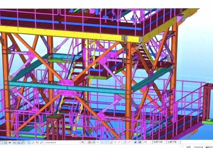
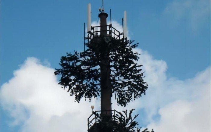
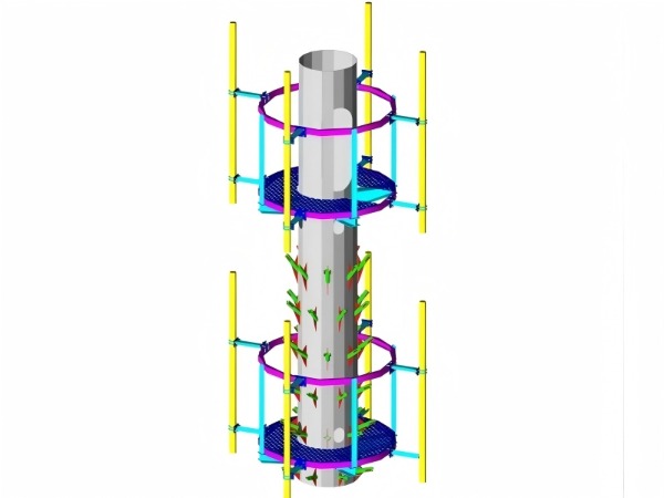
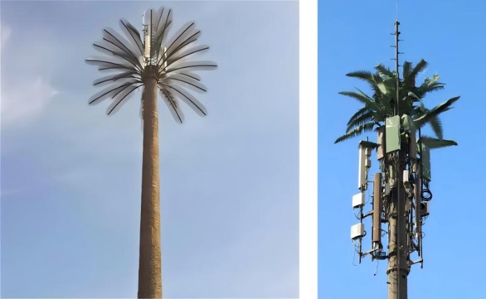
The camouflage tree tower represents one of the most sophisticated challenges in telecommunications infrastructure: creating a structure that simultaneously disappears from human sight while remaining fully functional for radio signals. This requires navigating a fundamental engineering tension between electromagnetic performance and mechanical robustness.


palm tree tower


The Core Conflict

A camouflage tower must satisfy two diametrically opposed requirements:


Requirement Implication Challenge
RF Transparency Materials must allow radio waves to pass without attenuation or distortion Requires low dielectric constants, minimal conductive elements, thin cross-sections
Structural Integrity Must withstand wind, ice, seismic loads for decades Requires dense materials, robust connections, substantial cross-sections


The engineer's task is to reconcile these within a structure that convincingly mimics a living tree.


Material Selection: The First Balancing Act

Fiber-Reinforced Polymer (FRP) and High-Density Polyethylene (HDPE) have emerged as the industry standards for camouflage elements because they uniquely bridge this divide:

  1. · Dielectric properties: FRP (ε_r 3.5-4.5) and HDPE (ε_r 2.3-2.5) allow signal passage with minimal loss

  2. · Non-conductive: No metallic content means no parasitic antenna effects

  3. · Structural capability: Glass fibers provide strength without conductivity (unlike carbon fiber)

  4. · UV resistance: Modern formulations survive decades of sun exposure


Manufacturers specify 95-99% RF transparency, meaning signal loss through foliage and bark is kept to 1-5% of original power—imperceptible to network performance.


bionic tree tower


The Branch Attachment Challenge

Each branch represents a structural weak point that must transfer wind loads to the core tower without failing. Engineers solve this through:

  1. · Reinforced mechanical connections: Branches attach to protruding receptors on the monopole via both mechanical fasteners and adhesives

  2. · Load-testing: Designs are validated for winds exceeding 80 mph (130 km/h) , with premium ratings up to 250 km/h for typhoon zones

  3. · Ice load accommodation: Branches must survive radial ice accumulation without becoming brittle


The Antenna Positioning Imperative

The steel monopole core is inherently RF-opaque—it cannot be made transparent. Therefore, antennas must be positioned outside the trunk, within the branch canopy:

  1. · Branch-level mounting: Antennas are placed at the same height as surrounding branches, which conceal them visually while remaining RF-transparent
  2. · Strategic density: Branch spacing must balance concealment (requires density) against wind load and cost (sparsity)

  3. · Vertical tiering: Multiple antenna arrays require corresponding branch arrangements at each height


This geometry is the fundamental insight: the camouflage conceals the antennas, not the tower itself. The opaque steel remains hidden behind the visual distraction of branches.


palm tree tower


Environmental Durability

The camouflage system must survive the same environmental loads as the tower it conceals:

  1. Wind: Branches engineered to flex without failing, shedding energy rather than resisting it

  2. Ice: Material flexibility (especially HDPE) helps shed accumulations before critical loads develop

  3. UV: Stabilizers and inhibitors in the polymer matrix prevent embrittlement and fading over decades

  4. Fire: Materials meet Class A or Class 1 ratings, self-extinguishing without contributing to flame spread


The bark-like coating—applied over galvanized steel—is a multi-layer system with embedded texture from real tree molds, finished with UV-resistant topcoats rated for 20-30 year service life.


The Optimization Summary


Element RF Requirement Structural Solution
Branches Non-conductive polymer HDPE/FRP with UV stabilizers, engineered attachments
Bark No conductive pigments Multi-layer epoxy/polyurethane over steel
Core Tower Opaque—must be avoided Antennas positioned at branch level, not inside trunk
Attachments Non-conductive where possible Polymer brackets or shielded steel

Conclusion

The camouflage tree tower is not a compromise between RF transparency and structural integrity—it is an optimization. By selecting inherently suitable materials, positioning antennas intelligently, and engineering attachments for extreme loads, manufacturers create structures that satisfy both requirements simultaneously. The result is infrastructure that truly disappears: invisible to observers, transparent to signals, and impervious to the elements.


 Learn more at   www.alttower.com


Contact Us

The telecommunications industry is witnessing a fundamental realignment of infrastructure roles. For decades, the architecture of connectivity was vertically integrated: a single tower, a single operator, a single purpose. Today, a new division of labor is emerging—one that leverages the unique strengths of both space-based and terrestrial assets. In this paradigm, satellite constellations like Starlink dominate wide-area coverage and backhaul, while ground-based towers handle low-latency AI inference and indoor penetration. This is not a competition for supremacy but a strategic specialization driven by immutable physics and economics.


monopole towers


The Spectrum Reality: Why Satellites Can't Match Terrestrial Capacity

The most fundamental constraint on satellite communication is spectrum. AT&T CEO John Stankey recently delivered a "physics lesson" to the industry, highlighting a stark numerical reality: terrestrial mobile network operators have access to approximately 300 megahertz of spectrum per cell site, which is more than triple the 80 megahertz that SpaceX can provide from its entire satellite constellation.

This 80 MHz allocation must be shared across a spot beam covering a radius of roughly 20 miles—compared to a terrestrial cell site's 2-2.5 mile radius . The implication is inescapable: spectral density—bandwidth per user per square kilometer—is fundamentally limited in satellite systems. As Stankey noted, this creates "a weaker uplink" and makes a like-for-like replacement of terrestrial networks by satellites "a hard putt" .

An Analysys Mason report quantified this limitation, finding that Starlink's constellation could provide maximum downlink capacity per beam of only 18.3 Mb/s using 5 MHz of spectrum "under optimal conditions"—capacity that must be shared among all users under that beam.


starlink


The Indoor Coverage Divide: Where Physics Meets Architecture

Satellite signals face another immutable constraint: building penetration. Research has consistently demonstrated that higher frequencies—precisely those used by modern satellite systems for bandwidth—suffer disproportionately from wall attenuation.

Frequency-Dependent Penetration Loss

Academic studies of satellite-to-indoor propagation at L-, S-, and C-bands have documented significant building penetration losses that increase with frequency . A comprehensive measurement campaign using a remote-controlled airship as a pseudo-satellite found a pronounced elevation-angle dependence in signal loss, with non-line-of-sight conditions within buildings presenting formidable challenges .

For low-Earth orbit (LEO) satellite signals, penetration into deep indoor environments remains problematic. However, research has shown that lower-frequency constellations like Orbcomm (operating in the VHF band at 137-138 MHz) can achieve remarkable indoor penetration—even reaching basements—while higher-frequency systems struggle . This underscores the fundamental trade-off: lower frequencies penetrate buildings but offer limited bandwidth; higher frequencies deliver capacity but stop at the window.


monopole towers


The Glass Ceiling

Modern building materials compound the problem. Low-emissivity (low-E) coated glass, ubiquitous in energy-efficient construction, can attenuate satellite signals by 4.2 dB or more at Ku-band frequencies . Double-silver coated glass can increase attenuation to 3.5 dB, and when signals must pass through at oblique angles—typical for satellites at lower elevation angles—polarization loss can spike by 40% .

AST SpaceMobile, a direct-to-cell satellite provider, acknowledges that achieving reliable indoor reception requires significant signal strength. While 35 dBi may suffice for outdoor and vehicle connectivity, reliable light indoor penetration demands 40 dBi—a threefold increase in signal power—and next-generation satellites aim for 46 dBi to compensate for building loss .


The Latency Imperative: Why AI Computation Must Stay Grounded

The emerging era of edge AI and real-time applications introduces another constraint: latency. While LEO satellites have dramatically reduced round-trip times compared to geostationary orbit—Starlink achieves latencies of 31 milliseconds in ideal conditions —this still exceeds the single-digit millisecond requirements of autonomous systems, industrial robotics, and augmented reality.

Stankey emphasized this point, noting that satellite upstream links are "inherently going to be a more fragile upstream uplink" than terrestrial networks that connect to fiber quickly . For AI inference—where split-second decisions matter—getting data onto fiber as rapidly as possible is paramount. Terrestrial towers with fiber backhaul provide the low-latency, high-reliability path that distributed intelligence demands.


monopole towers


The New Division of Labor: Specialized Roles for a Converged Network

These physical constraints naturally suggest a functional specialization:

Satellites: The Wide-Area Transport Layer

LEO constellations excel at what terrestrial infrastructure cannot economically achieve: connecting the unconnected. For maritime vessels, aircraft, remote wilderness areas, and disaster zones, satellites are the only viable solution. They also serve as high-capacity backhaul for terrestrial sites in challenging locations .

ABI Research projects that the direct-to-cellular market will generate $11.6 billion in revenue by 2030, with IoT applications alone contributing $4 billion . As Stankey noted, satellite may prove superior for "assets that move all over the globe, like container ships"—applications where global mobility trumps local capacity .

Terrestrial Towers: The Capacity and Computation Layer

Ground-based infrastructure—the monopoles, lattice towers, and small cells that form the subject of this blog series—will remain the workhorses of high-density connectivity. With 300+ MHz of spectrum per site, fiber backhaul, and proximity to users, terrestrial towers deliver:

  1. Massive capacity for dense urban environments

  2. Reliable indoor coverage through low-frequency bands and distributed antenna systems

  3. Ultra-low latency for edge computing and AI inference

  4. Support for massive MIMO and beamforming technologies that maximize spectral efficiency


lattice tower


The Convergence Opportunity: Hybrid Networks

The true promise lies not in choosing one architecture over another but in seamless integration. Starlink already operates over 8,000 satellites in orbit, with more than 600 supporting direct-to-device services . Terrestrial operators are partnering with satellite providers—AT&T with AST SpaceMobile, others with Starlink—to create networks where devices intelligently select the optimal path based on location, activity, and requirements.

This hybrid model recognizes that:

  1. Outdoors and mobile may favor satellite connectivity

  2. Indoors and stationary demands terrestrial infrastructure

  3. Emergency scenarios require both, with automatic failover

  4. IoT applications may use satellite for remote reporting and terrestrial for dense sensor networks


Conclusion: Complementary, Not Competitive

The new division of labor in telecommunications infrastructure is not a battle for supremacy but a recognition of complementary strengths. Satellites, with their global reach and declining launch costs, will dominate the wide-area transport layer—connecting the remote, the mobile, and the underserved. Terrestrial towers, with their spectral abundance, building penetration, and fiber proximity, will anchor the capacity layer—delivering the bandwidth and low latency that AI, streaming, and real-time applications demand.

As one industry analyst noted, the market is "evolving quickly, and many services are finding enhanced deployment through strategic alliances" . The winners in this new landscape will be those who embrace specialization, integrate seamlessly across domains, and respect the physical constraints that ultimately govern all communication.

The sky is not the limit—it is one part of a unified system that extends from low-Earth orbit to the smallest indoor femtocell, each element performing the role for which physics and economics have best suited it.


 Learn more at   www.alttower.com


Contact Us

The telecommunications industry stands at the precipice of a fundamental transformation. As 5G matures and the vision of 6G takes shape, the network edge is becoming intelligent. The future is not merely about connectivity—it is about computation at the edge, where AI inference happens milliseconds from the user, enabling autonomous systems, immersive reality, and real-time industrial control. This vision demands that processing power migrates from distant cloud data centers to the very base of the tower. But this raises an urgent structural question: Can today's slender monopoles bear the weight of tomorrow's AI?


monopole towers


The New Weight: Edge Computing's Structural Demand

The integration of edge computing infrastructure into tower sites represents a paradigm shift in loading conditions. Traditional tower-mounted equipment—antennas, remote radio units (RRUs), and microwave dishes—is measured in kilograms. A typical 5G Massive MIMO antenna weighs 40-47kg . A full complement of sector antennas might total 200-300kg per platform.

Edge computing is different. It requires physical infrastructure: servers, storage, power distribution, and cooling systems. These are not lightweight appendages; they are substantial installations that, in a traditional data center context, demand floor loading capacities of 16 kN/m² or more . This figure—equivalent to approximately 1,600 kg per square meter—is not arbitrary. It reflects the weight density of fully populated server racks, battery backups, and the structural frames that support them.

For a monopole tower, this presents an unprecedented challenge. The question is not whether the tower can support a few additional kilograms—it is whether its foundation, shaft, and connection points can bear the concentrated weight of a micro data center at its base or, in more aggressive designs, mounted on its shaft.


Existing Capacity: The Monopole's Load Envelope

To understand the gap, we must first understand what today's monopoles are designed to carry. The loading capacity of a monopole depends critically on its height and structural design :


Tower Height Class Typical Equipment Load Capacity
Under 100 feet (30m) 500-1,000 lbs (227-454 kg)
100-150 feet (30-45m) 1,000-2,000 lbs (454-907 kg)
Over 150 feet (45m+) 2,000-5,000+ lbs (907-2,268 kg)
monopole towers

Extra-heavy-duty towers, specially engineered for extreme loads, can be rated for over 10,000 lbs (4,500 kg) . These capacities, however, assume that loads are distributed appropriately—typically antenna masses mounted on platforms along the upper shaft, with their weight transferred through the structure to the foundation.

The key observation is that even the largest monopoles have total equipment load capacities measured in thousands of kilograms—not tens of thousands. A fully equipped edge micro data center, with its servers, power systems, and thermal management, could easily consume 30-50% or more of a medium tower's total capacity before any antennas are installed.


The Structural Loading Gap: Comparing Requirements

The disparity between traditional antenna loads and edge computing requirements becomes stark when expressed in engineering terms.

Traditional Antenna Loads:

  1. · Distributed along upper shaft (favorable for moment distribution)

  2. · Low mass density per unit area

  3. · Dynamic wind loads dominate over static weight

  4. · Point loads manageable through localized reinforcement

Edge Computing Loads:

  1. · Concentrated at base or lower shaft (more favorable location, but high magnitude)
  2. · High mass density requiring substantial floor space
  3. · Static gravity loads dominate structural demand
  4. · Requires dedicated support platform with load distribution

monopole structures


A typical edge data center module, even in compact form factors, might impose a base area load of 5-10 kN/m²—lower than a core data center's 16 kN/m², but still an order of magnitude higher than the distributed loads from antenna platforms . For a tower with a base diameter of perhaps 1-2 meters, the available footprint is limited, concentrating these loads further.


The Foundation Question

The most critical structural element for bearing additional weight is not the tower shaft—it is the foundation. Monopole foundations are typically designed as rigid concrete piers or drilled shafts, sized to resist overturning moments from wind and the tower's self-weight .


monopole mast


Adding a multi-ton edge computing load at the base fundamentally alters the foundation's demand:

  1. · Increased compressive stress on the concrete and soil
  2. · Potential settlement if soils are compressible
  3. · Changed load eccentricity affecting moment distribution

Foundations are the most expensive and least accessible part of a tower to modify. A monopole designed without margin for significant additional base weight may face a hard constraint: the foundation cannot safely carry more load, regardless of what the shaft can support.


Reinforcement Strategies: Raising the Capacity Ceiling

For towers with structural margin—or for those where the foundation can accommodate additional load—several reinforcement strategies exist to increase shaft capacity.

1. External Steel Reinforcement (Field-Applied)

A patented method involves attaching vertical flat bars to the tower's exterior using one-sided bolts . These bars, typically steel, are installed continuously up the tower length, with joining plates connecting sections. The reinforcement works by sharing bending moments, effectively increasing the section modulus of the tower. This approach can be targeted to specific zones where additional equipment will be installed .

2. Carbon Fiber Reinforced Polymer (CFRP) Wrapping

Research at North Carolina State University has demonstrated that high-modulus carbon fiber polymers can increase monopole flexural capacity by 20-50% . This technique involves bonding CFRP sheets or strips to the tower's exterior, adding strength and stiffness with minimal weight penalty. The CFRP works compositely with the steel, resisting tensile stresses and delaying yielding. For towers where weight addition is the primary concern, CFRP offers an elegant solution .

3. Internal Stiffening and Bracing

For multi-sided monopoles, internal diaphragms or bracing can be added to increase local stability and global stiffness. This is most feasible during manufacturing but can be retrofitted in some designs.


monopole mast


Design Standards: Built for Today, Not Tomorrow

Current design standards for monopole towers—whether Eurocode , TIA , or GB standards —are focused on traditional telecommunications loads. Eurocode EN 1993-3-1 provides specific guidance for towers and masts, but its load combinations assume antenna and wind loads as the primary drivers . The safety factors embedded in these standards (typically 1.5-2.5 for ultimate loads) provide some margin, but this margin was never intended to accommodate an entirely new class of equipment .

The TIA has recently updated its data center standard (TIA-942) to address edge computing, recognizing that "data processing is increasingly happening at the Edge" and that "data- and compute-intensive AI applications require... significantly higher cabling and rack power densities" . However, this standard applies to the data center facility itself—not to the tower that must support it. A new class of design standard is needed, one that bridges telecommunications tower engineering and data center facility requirements.


Designing for the AI Era: New Monopole Specifications

For new deployments where edge computing integration is anticipated, the design must evolve:

  1. Increased Base Strength: Specify thicker steel in lower sections and larger base plates to accommodate concentrated loads.

  2. Integrated Equipment Platforms: Design the tower with dedicated structural supports for edge computing modules, integrated into the initial foundation design.

  3. Higher Safety Factors: Consider increasing the ultimate load safety factor beyond the standard 1.5-2.5 to provide margin for unknown future equipment .

  4. Modular Foundation Design: Size foundations with reserve capacity for additional dead load, anticipating that the tower's function may evolve over its 30-50 year lifespan.


Conclusion: The Structural Crossroads

The convergence of edge AI and telecommunications infrastructure presents the tower industry with a fundamental challenge. Today's monopoles, engineered for the relatively modest loads of antennas and RRUs, were not designed to host micro data centers. Their load capacities—ranging from 500 to 5,000 pounds—are measured in the same order of magnitude as the equipment they may soon be asked to support .

monopole steel tower

The path forward is not binary. Many existing towers can be reinforced through external steel members or advanced composites like CFRP, achieving 20-50% capacity increases . Foundations, however, remain the critical constraint—once poured, they are difficult and expensive to upgrade.

For new deployments, the message is clear: design for the AI era from day one. Specify higher-grade steels, increase base section thickness, and—most critically—pour foundations with reserve capacity for the unknown computational loads of tomorrow. The tower that hosts both antennas and AI will be the most valuable asset in the network. The question is whether today's monopoles are ready to bear that weight.


 Learn more at   www.alttower.com


Contact Us


In the relentless pursuit of expansive wireless coverage—for broadcasting, long-haul microwave links, or next-generation mobile networks—height is the ultimate asset.

guyed mast tower


It extends line-of-sight, clears terrain obstacles, and maximizes the economic value of a single site. However, for traditional self-supporting towers (monopoles or lattice), increasing height incurs a crippling economic penalty: material costs and foundation demands escalate exponentially. Beyond approximately 150-180 meters, the conventional paradigm breaks. This is where the guyed mast tower asserts its engineering and economic supremacy. By masterfully leveraging tensioned cables, it defies gravity not through brute mass, but through intelligent force distribution, fundamentally altering the relationship between height and cost for structures reaching 200, 300, and even 400 meters.

This blog deconstructs the core principles that allow guyed towers to achieve extreme heights with remarkable material economy.


The Cost-Height Conundrum: Why Self-Supporting Towers Hit a Wall

For a self-supporting tower, every additional meter of height must resist increasing overturning moments from wind. This resistance is provided solely by the tower's own bending stiffness and the foundation's ability to resist uplift. The result is a cubic relationship between height and material requirement. Doubling the height of a freestanding tower typically requires approximately eight times the material in the lower sections to maintain stability. Foundations become massive, deep-piled structures to prevent tipping. This makes self-supporting designs beyond 180-200m prohibitively expensive and logistically daunting.

guyed wire tower


The Guyed Mast Paradigm: Replacing Bending with Tension

The guyed mast inverts this problem. It is a slender, vertical column (the mast), stabilized not by its own girth, but by a system of high-strength steel guy cables anchored to the ground at radial distances. This system transforms the primary structural action from bending (inefficient) to axial compression and tension (highly efficient).


  1. · Load Transformation: When wind pushes against the mast, it attempts to bend it. The guy cables on the leeward side resist this motion by going into tension. This tension pulls the mast back toward vertical, while the windward cables slacken slightly. The mast itself primarily experiences axial compression, a load case where steel performs with exceptional efficiency.

  2. · The Power of Pre-Tension: The cables are not installed slack. They are pre-tensioned during erection to a calculated load. This initial tension ensures all cables remain taut under varying wind directions, eliminating destructive dynamic slack-tighten cycles that cause fatigue. Pre-tension also increases the system's natural frequency, improving its dynamic stability.


Core Engineering Principles Enabling Economic Height

1. Material Efficiency and Optimal Force Resolution
The mast can be an incredibly slender steel tube or lattice section because it does not need massive bending strength. Its primary job is to carry its weight and the equipment load as a column. The immense lateral wind force is resolved into manageable axial forces: compression in the mast and tension in the cables. High-strength steel cable, with a tensile strength far exceeding that of structural steel used in compression, handles this tension with minimal material. This separation of functions—compression vs. tension—allows each material to be used where it performs best, leading to a structure that is often less than half the weight of an equivalent-height self-supporting tower.

guyed wire tower

2. The Geometry of Stability: Anchor Radius and Guy Levels
The system's stiffness and economy are dictated by geometry.

  1. Anchor Radius: The distance from the mast base to the ground anchors. A larger radius allows the guy cables to act at a more favorable angle, reducing the tension required in the cables to counteract a given wind moment. This is a key economic lever.

  2. Multiple Guy Levels: Tall masts employ several sets of guy cables attached at different heights. This breaks the mast into a series of shorter, effectively braced columns, preventing global buckling and minimizing mast diameter. The optimal number and spacing of guy levels are calculated to minimize total material (mast + cable) cost.

3. Foundation Simplification: From Uplift to Gravity
This is a transformative cost advantage. A self-supporting tower foundation must be designed as a moment-resisting system, fighting enormous uplift and overturning forces with deep piles or massive concrete counterweights. A guyed mast foundation is simplified:

  1. Mast Foundation: Primarily carries a straightforward vertical compressive load (the weight of the structure). It is a simple slab or pile cap.

  2. Anchor Foundations: These are designed to resist pure vertical uplift from the cable tension. While significant, designing for pure uplift using dead weight (concrete blocks) or rock anchors is fundamentally simpler, requires less complex reinforcement, and is far more cost-effective per kilonewton of resistance than a moment-resisting foundation.

4. Aerodynamic and Dynamic Mastery
At extreme heights, dynamic response is critical.


  1. Aerodynamic Damping: The system has inherent damping. Energy from wind gusts is dissipated through slight, elastic stretching and vibration of the long cable runs.

  2. Avoiding Resonance: The fundamental natural frequency of a well-designed guyed mast is typically very low (e.g., 0.2-0.5 Hz), safely below the frequency of vortex shedding from the slender mast and the forcing frequencies of wind turbulence. Supplemental dampers (e.g., Stockbridge dampers on cables) can be added to suppress specific wind-induced vibrations.


guyed wire tower


Breaking the Linear Cost-Height Relationship

The combined effect of these principles is a dramatic flattening of the cost curve. Where a self-supporting tower's cost escalates exponentially, the guyed mast's cost increases at a rate much closer to linear with height. The additional material for a taller guyed mast is primarily incremental: more length of the slender mast section and longer guy cables. The fundamental engineering components—the concept of load transfer via tension, the foundation types—do not change, allowing for scalable design.

Comparative Snapshot: 250m Tower


  1. · Self-Supporting Lattice Tower: Would require a massive, tapered lattice base with enormous member sizes, a extraordinarily complex and deep foundation system, and total steel weight potentially exceeding 1,500 tons.

  2. · Guyed Mast: Would employ a relatively uniform, slender tubular mast (perhaps 2-3m diameter), 3-4 levels of guy cables, and a set of gravity block or anchor foundations. Total steel weight might be under 500 tons. The cost difference can be a factor of 2-3x in favor of the guyed solution.


guyed wire antenna tower


Conclusion: The Intelligent Path to the Stratosphere

Guyed communication towers represent a triumph of principle-based engineering over brute force. By understanding and harnessing the efficient load-carrying mechanisms of tension and compression, and by using the ground itself as a key structural component via anchors, they solve the problem of extreme height in the most materially economical way possible.

They are not suitable for every site—requiring significant land for anchor radii—but where space allows, they are the undisputed, most economical solution for piercing the 200-meter barrier and beyond. In defying gravity to connect the world, they prove that the most powerful engineering isn't about using more, but about using force more intelligently. For reaching the skies in pursuit of coverage, the guyed mast remains the most rational, gravity-defying choice.


 Learn more at   www.alttower.com


Contact Us

keyboard_arrow_up