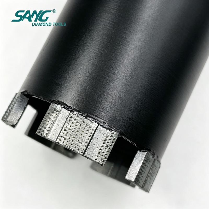
SANG ARIX Segment Diamond Saw Blade For Cutting Reinforced Concrete
It's 7 AM on a road repair job. You have a concrete saw blade in the saw and an asphalt patch to cut. The temptation to "just make it work" is real. But experienced contractors know: the wrong blade doesn't just perform poorly — it self-destructs, and takes part of your profit margin with it.
Why Asphalt and Concrete Demand Different Blades These two materials sit at opposite ends of the material science spectrum: Asphalt: Soft, sticky, loaded with abrasive aggregate. Generates heat rapidly and clogs tooling. Concrete: Hard, brittle, with dense aggregate that demands continuous diamond self-sharpening. Every dimension of blade design reflects this fundamental difference.
Difference 1: Bond Hardness — Intentionally Reversed This is the most counterintuitive rule in blade selection: Asphalt blade → Hard Bond Concrete blade → Soft Bond (for hard concrete) Why? Asphalt's abrasive aggregate would rapidly consume a soft bond matrix, ejecting diamonds before they've done meaningful work. A hard bond resists this erosion and keeps diamonds working longer. Using a soft-bond concrete blade on asphalt: the matrix is consumed within minutes, diamonds shed wastefully, and blade life drops by 70% or more.
Difference 2: Diamond Grit Size Asphalt blades use larger grit (lower mesh) diamonds — larger contact areas cut through sticky binder without getting gummed up.
Concrete blades use finer grit (higher mesh) diamonds — more particles per segment maintain cutting pressure against hard aggregate.
Difference 3: Segment Geometry — Heat Is the Real Enemy Asphalt contains petroleum-based binder. When it heats up, it liquefies and adheres to the blade segments — a phenomenon called "blade loading." Asphalt blades are designed with: Wider gullets for faster slurry and debris ejection Segment geometry that minimizes sticky material buildup
Difference 4: Core Thickness
Concrete's hard aggregate generates higher impact forces, requiring a thicker, stiffer steel core to prevent warping. Asphalt's softer composition produces less impact stress, but the blade must remain stable as asphalt softens under heat and applies lateral forces.
Difference 5: The Real Cost of the Wrong Blade
Wrong Choice
Result
Estimated Cost Impact
Concrete blade on asphalt
70% shorter life, wasted diamonds
2–3x higher tooling cost
Asphalt blade on concrete
Slow cutting, core overheating
50%+ efficiency loss
When a "Universal" Blade Makes Sense For road repair projects that alternate between concrete and asphalt cuts, SANG offers a hybrid road blade with a composite bond formulation. It delivers acceptable performance on both materials — best suited for lower-volume jobs where carrying two blade types isn't practical.
SANG Road-Specific Blade Lineup SANG Asphalt Blade: Hard bond + wide gullets for high-abrasion aggregate SANG ARIX/Turbo Concrete Road Blade: Soft/medium bond + laser welding for dense reinforced pavements
SANG Hybrid Road Blade: Composite formula for mixed-material repair projects
Why Leading Global Contractors Trust SANG SANG Diamond Tools — A Legacy of Leadership Since 1993
Top 10 Industry Leader
Established in 1993, SANG is recognized as a Top 10 Manufacturer in China's diamond tool industry. With an annual tax contribution reaching millions, we are a fiscally strong and reliable partner you can trust for long-term supply.
Scientific Innovation (PhD R&D Team)
Innovation is in our DNA. Our R&D center is led by multiple PhDs from prestigious universities, focusing on molecular-level bond design. We don't just sell tools; we provide Exclusive Construction Solutions tailored to your specific job site challenges.
Large-Scale Production & Capacity
With a workforce of 50+ dedicated workshop employees, SANG operates high-capacity automated production lines. We guarantee short lead times and the ability to fulfill container-load orders without compromising quality.
Globally Validated Quality
We hold numerous national industry patents and a comprehensive range of international certificates for our diamond saw blades and grinding tools. Our quality is validated by the most stringent markets in North America and Europe.
Professional Multilingual Communication
Communication is the key to successful partnership. Our sales team consists entirely of English Major (TEM-8) graduates. Furthermore, we offer support in various minority languages (including French, Persian, Spanish, etc.), ensuring zero-barrier communication and precise requirement handling.
On-Site & Remote Technical Support
We stand behind our products. Our technical engineers offer both online video consultations and offline on-site support to assist with machine calibration, tooling selection, and troubleshooting at your project site.
When you choose SANG, you are not just buying a DIAMOND TOOLS; you are partnering with a 30+years industry powerhouse dedicated to your project's success.
For more details about diamond saw blade or polishing tool,contact us
WWW.SANGTOOLS.COM
INFO@SANGTOOLS.COM
Quick Answer Yes — but only if you choose the right bit. A standard sintered core bit can cut reinforced concrete, but it dulls quickly on rebar, overheats in dry conditions, and loses segment bond strength under continuous load. A Laser Welded ARIX Technology Segment Diamond Core Drill Bitsolves all three problems simultaneously:
ARIX 3D segment geometry locks diamond particles in a three-dimensional matrix, exposing fresh cutting surfaces continuously instead of wearing flat.
Laser welding at 1,300–1,500 °C fuses the segment directly to the steel barrel — no braze alloy filler, no heat-damaged diamonds, no segment drop-off under vibration.
Dual wet/dry compatibility means the same bit works on a water-cooled rig for deep structural walls and a handheld dry drill for tight interior spaces.
If your project involves C30–C60 reinforced concrete with embedded rebar, this guide will help you spec the right bit, avoid the three most common procurement mistakes, and understand why bond type is more important than price per unit.
1. Why Reinforced Concrete Is a Different Problem
Reinforced concrete combines two materials with opposite wear characteristics:
Material
Hardness (Mohs)
Effect on Diamond Bit
Cured concrete (C40)
6–7
Abrasive — wears bond matrix
Steel rebar (Grade 60)
5–6
Impact-resistant — dulls diamond grit
Aggregate (quartz/granite)
6.5–7
High abrasion — accelerates segment wear
A bit optimized for concrete alone uses a hard bond to survive abrasion — but a hard bond glazes on rebar, causing the bit to skid rather than cut. A soft bond cuts rebar easily but wears out 30–50% faster in high-aggregate concrete. ARIX technology resolves this trade-off by changing the geometry of the diamond distribution, not just the bond hardness.
2. What ARIX Technology Actually Means (And What It Does Not) ARIX is a patented three-dimensional segment architecture developed for high-performance diamond tooling. It is not a brand of diamond grit or a coating — it is a structural design for how synthetic diamond particles are arranged within the metal bond matrix.
Standard Segment vs. ARIX Segment
Feature
Standard Flat Segment
ARIX 3D Turbo Segment
Diamond distribution
Single horizontal layer
Multi-layer 3D matrix
Wear pattern
Uniform flat surface → polishing
Progressive exposure of fresh diamond
Self-sharpening
Low — requires dressing stone
High — auto-exposes new cutting edges
Cutting efficiency at depth
Decreases significantly after 50mm
Remains consistent to full barrel depth
Heat generation
Higher — flat surface creates friction zone
Lower — 3D profile improves chip evacuation
Rebar crossing
Segment may glaze
Turbo geometry maintains bite through steel
The turbo profile of an ARIX segment creates micro-channels between raised diamond ridges. These channels clear swarf and concrete dust during rotation, reducing friction heat by an estimated 15–25% compared to a flat segment under equivalent load. For procurement managers: this directly translates to fewer bit changes per shift and measurable reduction in downtime cost.
3. Why Laser Welding Matters More Than You Think Most diamond core bits in the mid-price range use high-frequency sintering or silver-braze bonding to attach segments to the steel barrel. Both methods work — until conditions get demanding.
Laser welding does not use a filler alloy. The laser melts a micro-zone of both the segment base and the barrel steel simultaneously, creating a molecular-level fusion bond. The result:
Segment shear strength is 40–60% higher than brazed bonds under lateral stress
No braze alloy layer to crack under thermal cycling (wet/dry switching)
Safe for use with high-torque hydraulic drilling rigs without segment detachment risk
At SANG Diamond Tools, our laser welding process is calibrated at our Quanzhou facility using automated laser parameters set by our PhD R&D team. Every barrel undergoes post-weld pull-test inspection before shipment.
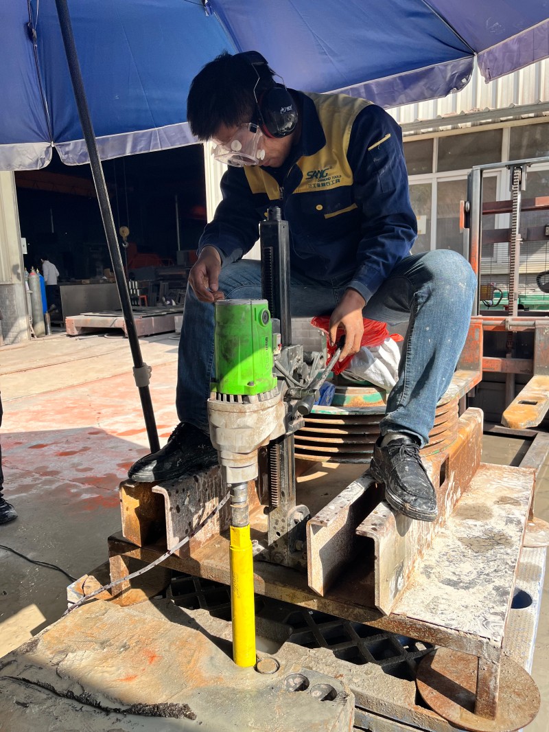
4. Dry vs. Wet Cutting: When to Use Which Mode One of the most common procurement questions we receive: "Do I need to order separate bits for dry and wet drilling rigs?"
With a standard bit — yes. With a properly designed ARIX laser welded bit — no.
Wet vs. Dry Mode Decision Guide
Factor
Wet Drilling
Dry Drilling
Bit cooling
Water coolant via centre flush
Air + segment geometry
Dust control
Excellent — slurry contains dust
Requires dust shroud or extractor
Drilling speed
Higher — less heat buildup
Slightly slower; limited to shorter runs
Interior use
Messy — water management needed
Clean — preferred for occupied buildings
Rebar depth
Ideal for deep walls (>300mm)
Suitable to ~200mm in most configurations
Bit wear
Slower — water lubricates diamond contact
Faster if run too long without pause
SANG ARIX bit compatibility
Full — centre water flush compatible
Full — turbo channels provide air cooling
Practical rule: Use wet mode for structural drilling in walls, slabs, and foundations deeper than 200mm. Switch to dry mode for MEP rough-in, anchor bolt installations, and any work in occupied or finished interior spaces.
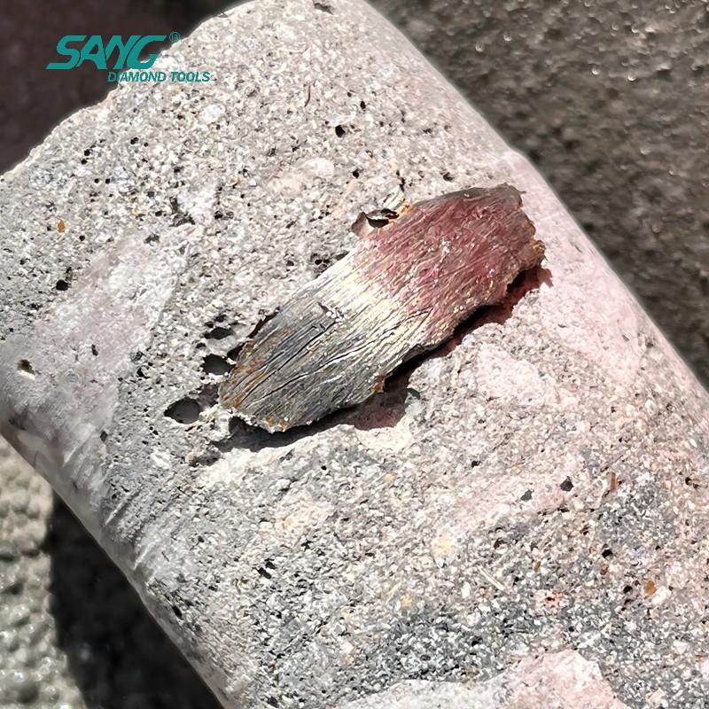
5. Real Project Case: High-Rise MEP Core Drilling, United States Project type: 42-story residential tower, mechanical/electrical/plumbing rough-in Material: C45 reinforced concrete shear walls, rebar density ~18 kg/m³ Requirement: 200 core holes of 82mm diameter through 300mm walls, 4-week schedule Tool used: SANG 82mm Laser Welded ARIX Core Bit, wet mode, hydraulic rig Results observed by the site contractor:
Average holes drilled per bit before segment wear: 210 holes (vs. 130–150 with competitor sintered bits previously used)
No segment detachment across entire run
Core extraction clean — no spalling at hole perimeter
Schedule completed 3 days ahead of target due to reduced bit change downtime
Note: Results are reported by the contractor team. Performance varies by concrete grade, rebar density, equipment power, and operator technique.
Why this matters for procurement: At 210 holes per bit vs. 150, a project requiring 1,000 holes needs 4.8 SANG bits vs. 6.7 competitor bits. At a realistic per-bit price difference of 15–20%, the SANG option delivers lower total cost per hole — not just lower per-bit cost.
6. Procurement Checklist: 8 Specifications to Confirm Before Ordering If you are a procurement manager, distributor, or project engineer ordering ARIX core bits for reinforced concrete work, confirm these eight parameters before placing an order:
Diameter — Match to the nominal hole size required (add 2–3mm for clearance fit on conduit/pipe)
Barrel length — Must exceed wall/slab thickness; standard lengths are 300mm, 450mm, 600mm
Connection thread — 1-1/4" UNC (most hydraulic rigs), M16, R½", or SDS adapter available
Wet / dry designation — Confirm centre flush port for wet mode; blank end cap for dry mode
Concrete grade — C30–C50: medium bond; C50–C60: soft-medium bond for ARIX geometry to self-sharpen
Rebar density — Heavy rebar (>20 kg/m³): specify laser welded; avoid brazed bits
Segment height — Standard 10mm for general use; 12mm for extended-run projects
Certification — Confirm ISO 9001 and any required market certifications (CE for EU, etc.)
SANG Diamond Tools provides technical specification sheets for all standard ARIX core bit configurations. Custom diameters from 14mm to 426mm are available with a minimum lead time of 7 working days.
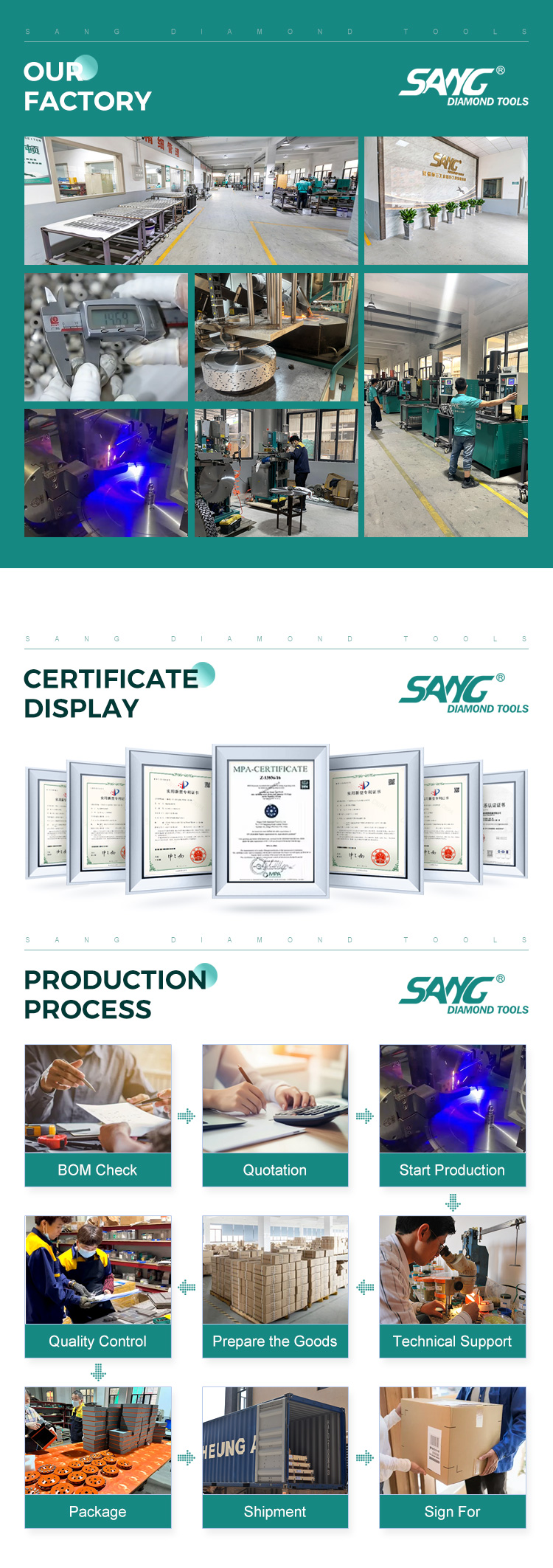
7. How SANG Designs ARIX Core Bits: The Engineering Perspective SANG Diamond Tools was established in 1993 in Quanzhou, Fujian — a region with a 30+ year manufacturing heritage in diamond tooling. We are recognized as a Top 10 Manufacturer in China's diamond tool industry, supplying distributors and contractors in 75+ countries including the United States, Germany, Australia, Italy, and Poland. Our ARIX core bit development process: Step 1 — Bond formula design Our R&D center, led by PhD researchers with backgrounds in materials science and powder metallurgy, designs bond matrices at the molecular level. Bond hardness is calibrated to match expected concrete grade ranges rather than applying a one-size formula.
Step 2 — Diamond selection and layer mapping Synthetic diamond grit is sorted by crystal shape and strength. The ARIX 3D layout places primary cutting diamonds at the segment crown and secondary diamonds in the mid-layer to activate as the primary layer wears.
Step 3 — Hot press sintering Diamond-metal powder mixes are sintered under controlled temperature and pressure. Parameters are logged per batch for quality traceability.
Step 4 — Laser weld attachment Segments are laser welded to the barrel steel in an automated fixture. Weld parameters are set per segment geometry and barrel wall thickness.
Step 5 — Post-weld inspection Each bit undergoes dimensional inspection, runout check (< 0.3mm TIR), and segment pull-test before packing.
This five-step process is why our ARIX bits consistently outperform imported alternatives in independent contractor field tests — and why we can offer container-load supply without quality variance between batches.
8. Core Key Takeaways Before you close this page, here is what matters most:
Reinforced concrete drilling requires a bit engineered for both abrasive concrete and impact-resistant rebar — standard bits are not designed for both simultaneously.
ARIX 3D segment geometry continuously exposes fresh diamond, maintaining consistent cut speed and reducing the glazing problem common with flat segments on rebar.
Laser welding at 1,300–1,500 °C creates a direct steel fusion bond — the segment cannot detach under the vibration and torque of hydraulic drilling rigs.
Dual wet/dry capability means one SKU covers both hydraulic wet rigs and handheld dry drills, simplifying procurement and reducing warehouse SKU count.
Total cost per hole — not unit price — is the correct metric for evaluating core bit procurement. More holes per bit = lower cost per hole even at a higher per-unit price.
SANG Diamond Tools has supplied ARIX core bits to contractors in 75+ countries since 1993, with full technical support from a PhD-led R&D team and certified quality management under ISO 9001.
9. FAQ
Q1: What is the difference between an ARIX core bit and a standard turbo core bit? A standard turbo bit has a shaped rim but uses a single-layer diamond distribution. An ARIX bit uses a three-dimensional multi-layer matrix where diamonds are positioned at different depths within the segment. As the outer layer wears, the next layer activates — this is what makes ARIX self-sharpening rather than self-dulling.
Q2: Can I use a laser welded ARIX bit on a standard handheld drill? Yes, provided the drill has sufficient torque (typically ≥900W for bits up to 82mm diameter) and you use the correct adaptor. For dry handheld drilling, keep individual runs under 30 seconds and allow the bit to cool between holes. For sustained drilling, a rig-mounted setup with water flush is recommended.
Q3: What concrete grades are SANG ARIX core bits rated for? Our standard ARIX range is designed for C30–C60 reinforced concrete. For ultra-high-strength concrete (C60+) or concrete with aggregate harder than 7 Mohs, contact our technical team for a custom bond specification.
Q4: How do I know if my current core bit glazing problem is a bond issue or a technique issue? If the bit cuts well for the first 10–15 holes then progressively slows, it is likely a bond-glazing issue (bond too hard for the concrete). If it cuts slowly from the first hole, it may be an RPM or water flow issue. SANG's technical team offers free remote video consultation to diagnose field problems.
Q5: What is the minimum order quantity for SANG ARIX core bits? Standard configurations are available from 1 piece for sample/trial orders. Container-load pricing is available for distributors. Custom diameter or thread specifications require a minimum of 10 pieces per SKU. Lead time: 5–7 working days for stock configurations, 10–15 days for custom.
Q6: Do SANG ARIX core bits come with CE or other certifications? Yes. SANG Diamond Tools holds ISO 9001 quality certification. Our diamond saw blades and grinding tools carry applicable international certifications. Specific certification documentation can be provided upon request for procurement or import compliance purposes.
Q7: What technical support does SANG provide after the sale? Our technical engineers provide online video consultations for bit selection, machine calibration, and troubleshooting. Offline on-site support is available for large project orders. Our sales team includes TEM-8 English graduates and staff fluent in French, Spanish, Persian, and other languages.
10. Ready to Spec Your Next Core Bit Order? If you are a contractor, distributor, or procurement manager sourcing ARIX core bits for reinforced concrete projects, SANG Diamond Tools offers:
Free technical consultation — describe your concrete grade, rebar density, wall thickness, and drilling rig; we will recommend the right specification
Trial sample orders — test performance on your job site before committing to project volumes
Custom diameter and thread configurations — 14mm to 426mm, all standard thread connections
Container-load supply — 50+ workshop staff, automated production lines, consistent quality across batches
Contact: info@sangtools.com | www.sangtools.com
SANG Diamond Tools — Established 1993 | Quanzhou, Fujian, China | Exporting to 75+ Countries Top 10 Diamond Tool Manufacturer in China | ISO 9001 Certified | PhD-Led R&D Team
Granite Drilling with a Vacuum Brazed Diamond Core Bit
A premium granite countertop can represent thousands of dollars in materials and labor. The final step — drilling faucet holes, soap dispenser openings, or filter connections — is also the moment when the most expensive mistakes happen. A single chipped edge can turn a flawless installation into a client dispute and a wasted slab.
The good news: with the right tool and the right technique, zero-chip granite drilling is entirely achievable. Here's the complete professional workflow from SANG Diamond Tools— refined over 33 years of manufacturing vacuum brazed diamond core drill bits for stone fabricators worldwide.
Step 1: Choose the Right Drill Bit — This Decision Determines Everything Granite drilling requires a wet diamond core drill bit — not a carbide hole saw, not a twist drill. The key selection criteria: Segment type: Turbo or ARIX Segment, shock-free entry Thin-wall design: Reduces friction surface area, generates less heat, produces smoother bore walls Diameter: Standard faucet holes are 35mm; soap dispensers typically 32mm — always verify hardware base dimensions first SANG wet granite core bits are available from 6mm to 150mm, silver-brazed segments, compatible with M14, 1/2" Gas, and 5/8"-11 connections.
Step 2: Mark and Template — Precision Before Power Mark the hole position on the underside of the slab using a pencil or wax marker. Apply masking tape over the drilling point on the top surface. This serves two purposes: Prevents the bit from skating across the polished granite surface at startup Protects the finish from incidental scratches during positioning For production environments drilling multiple identical positions, fabricate an acrylic or plywood jig to guarantee consistent hole placement across every slab.
Step 3: Start at Low RPM — Never Rush the Entry Set your drill or angle grinder to low speed (600–900 RPM). Begin with the bit tilted at 45° against the edge of the tape, walking a shallow starter groove. Then bring the bit to vertical. This entry technique eliminates skating on the polished surface — it's the single most consistent technique used by professional stone installers worldwide.
RPM Reference Guide:
Hole Diameter
Recommended RPM
≤ 30mm
800–1,200 RPM
30–60mm
500–800 RPM
60–100mm
300–500 RPM
> 100mm
≤ 300 RPM
Larger diameters require lower speeds. High RPM on large-diameter bits creates centrifugal forces that produce uneven segment loading — one of the primary causes of countertop chipping.
Step 4:Slow Down at Exit — The Most Critical Moment As the bit approaches full penetration (you'll feel resistance suddenly ease), immediately reduce RPM by 50% and lighten downward pressure. This is the highest-risk moment in the entire process. The bottom face of the granite loses its supporting material just before breakthrough, and any excess impact force will crack or chip the exit edge.
Professional technique: Place a scrap granite offcut against the underside of the drilling area, clamped or weighted in place. This "sacrificial backing board" absorbs exit impact and eliminates bottom-face chipping entirely.
Step 5: Clean, Inspect, and Finish After breakthrough: Flush the bore with clean water and inspect diameter Hone the bore walls progressively with 120-grit, then 400-grit diamond honing rods Apply granite-specific penetrating sealer to the bore edge to prevent moisture ingress over time.
4 Mistakes That Destroy Expensive Granite Slabs
Mistake
Consequence
Prevention
1. Using a carbide or twist bit
Immediate slab fracture, no recovery possible
Vacuum Brazed diamond core bits only
2.Skipping the sacrificial backing board
> 60% probability of bottom-face chip-out
Always use a waste offcut beneath
3. RPM too high for large holes
Radial cracking at bore edge from centrifugal stress
Keep RPM ≤ 500 for holes > 60mm
4. No slowdown at exit
Large chip-out on underside — visible from above
Feel for resistance drop, halve speed immediately
FAQ: Granite Drilling Questions
Q: Can I use a hammer drill on granite? A: Never. Hammer action shatters granite crystals. Use a standard rotary drill only — no percussion mode.
Q: My bit is spinning but not cutting into the granite. What's wrong?
A: The segments have glazed. Run the bit briefly on a dressing brick or concrete block to expose fresh diamonds. This typically restores full cutting performance in 15 seconds.
Why Leading Global Contractors Trust SANG
SANG Diamond Tools — A Legacy of Leadership Since 1993
Top 10 Industry Leader
Established in 1993, SANG is recognized as a Top 10 Manufacturer in China's diamond tool industry. With an annual tax contribution reaching millions, we are a fiscally strong and reliable partner you can trust for long-term supply.
Scientific Innovation (PhD R&D Team)
Innovation is in our DNA. Our R&D center is led by multiple PhDs from prestigious universities, focusing on molecular-level bond design. We don't just sell tools; we provide Exclusive Construction Solutions tailored to your specific job site challenges.
Large-Scale Production & Capacity
With a workforce of 50+ dedicated workshop employees, SANG operates high-capacity automated production lines. We guarantee short lead times and the ability to fulfill container-load orders without compromising quality.
Globally Validated Quality
We hold numerous national industry patents and a comprehensive range of international certificates for our diamond saw blades and grinding tools. Our quality is validated by the most stringent markets in North America and Europe.
Professional Multilingual Communication
Communication is the key to successful partnership. Our sales team consists entirely of English Major (TEM-8) graduates. Furthermore, we offer support in various minority languages (including French, Persian, Spanish, etc.), ensuring zero-barrier communication and precise requirement handling.
On-Site & Remote Technical Support
We stand behind our products. Our technical engineers offer both online video consultations and offline on-site support to assist with machine calibration, tooling selection, and troubleshooting at your project site.
When you choose SANG, you are not just buying a DIAMOND TOOLS; you are partnering with a 30+years industry powerhouse dedicated to your project's success.
For more details about diamond saw blade or polishing tool,contact us WWW.SANGTOOLS.COM INFO@SANGTOOLS.COM
Best Laser Welded ARIX Diamond Core Drill Bit for Reinforced Concrete | SANG Diamond Tools
Discover how laser welded ARIX diamond core drill bits improve drilling speed, lifespan, and safety in reinforced concrete. Learn how to choose the right core bit from SANG — 30+ years of manufacturing expertise, trusted in 75+ countries.
What Is the Best Laser Welded ARIX Diamond Core Drill Bit for Reinforced Concrete? A Complete Buyer's Guide By SANG Diamond Tools Technical Team | Est. 1993 | Top 10 Manufacturer in China | Trusted in 75+ Countries
Quick Answer If you're a procurement manager, contractor, or distributor evaluating core drill bits for reinforced concrete, here's what you need to know upfront:
Selection Criteria
Recommended Answer
Best segment technology
ARIX array-pattern diamond distribution
Best bonding method
Laser welding (not silver brazing)
Dry or wet cutting?
Both — dual-rated bits available
Can it drill through rebar?
Yes — ARIX maintains stable cutting through steel reinforcement
Bottom line:For reinforced concrete with rebar, a laser-welded ARIX segment core bit is not a premium upgrade — it is the baseline requirement for professional, safe, and cost-effective drilling.
Why Reinforced Concrete Is the Ultimate Test for Any Core Drill Bit Reinforced concrete is not a uniform material. It is an engineered composite of high-strength cement matrix, hard aggregate, and embedded steel reinforcement — and each element attacks your drill bit differently.
The Six Failure Modes in Reinforced Concrete Drilling
Failure Mode
Root Cause
Impact on Project
Segment glazing
Bond too hard for concrete hardness
Drilling stops entirely — must re-dress or replace
Rebar impact fracture
Silver-brazed bond cannot absorb shock
Segment detachment — safety incident
Thermal delamination
Heat exceeds brazed joint tolerance (~650°C)
Segment loss mid-hole — borehole damage
Bit vibration / drift
Uneven segment wear, unbalanced cutting
Hole deviation — structural non-compliance
Premature diamond burial
Random distribution leaves inactive zones
Slow drilling, high cost per hole
Core barrel warping
Thin-wall barrel under continuous rebar impact
Bit seizure in borehole — extraction cost
Standard silver-brazed bits with random diamond distribution are not engineered to handle this combination of failure modes simultaneously. ARIX technology and laser welding address each one at a fundamental manufacturing level.
What Is ARIX Technology? The Engineering Behind the Performance ARIX (Array Pattern) technology is a diamond placement methodology that positions individual diamond crystals in a precise, repeating three-dimensional geometric matrix within the metal bond segment — rather than the random distribution used in conventional segments.
Random vs. ARIX: A Side-by-Side Comparison
Performance Factor
Conventional Random Segment
ARIX Array Pattern Segment
Diamond placement
Irregular, clustered in zones
Precise geometric array, uniform spacing
Active cutting diamonds per pass
Variable — depends on which diamonds surface
Consistent — geometry guarantees exposure
Drilling speed
Medium, inconsistent
High, stable throughout tool life
Segment wear pattern
Uneven — causes vibration and drift
Uniform — maintains rotational balance
Rebar performance
Speed drops sharply at steel contact
Stable cutting rhythm maintained
Heat management
Localized hotspots at diamond clusters
Distributed — no single thermal concentration point
Tool lifespan vs. standard
Baseline
30–50% longer
Cost per hole drilled
Higher
Significantly lower
Hole wall quality
Standard roughness
Smoother bore wall
Why geometry matters at the microscopic level: Each diamond crystal in an ARIX segment has a defined neighborhood of bond matrix around it. When the segment contacts rebar, the impact load is distributed across multiple crystals simultaneously — no single crystal absorbs full shock. This is the physical reason ARIX bits survive rebar contact that destroys conventional segments.
SANG Engineering Note: SANG's PhD research team developed the ARIX matrix spacing specifically calibrated for the concrete density ranges and rebar configurations specified in ACI 318 (North America) and Eurocode 2 (Europe). The bond formulation is not adapted from a generic catalog — it is application-engineered for the markets where our customers operate.
Product Specifications: SANG Laser-Welded ARIX Core Drill Bit
Specification
Standard Options
Custom Available
Segment technology
ARIX array pattern, premium industrial diamond
Custom diamond grade on request
Welding method
High-precision laser welding
—
Cutting mode
Dry & Wet (dual-rated)
—
Diameter range
14mm – 300mm
Beyond 300mm on request
Connection types
1/2" Gas (BSP), 5/8"-18 UNC, 1-1/4" UNC, SDS-Max, SDS-Plus, M22
Non-standard threads on request
Barrel lengths
300mm / 400mm / 450mm / 500mm/ 600mm
Extended lengths on request
Segment height
10mm / 11mm / 12mm
Application-matched on request
Bond hardness
Soft / Medium / Hard
Custom formulation for specific concrete grades
Target material
Reinforced concrete, rebar-dense structures, hard aggregate
—
Certifications
ISO 9001, CE, National Industry Patents (CN)
—
OEM / Private label
Available
Contact SANG sales team
Selecting the Right Specification: A Step-by-Step Framework Step 1 — Define Your Hole Diameter
Diameter
Typical Application
32mm
Plumbing pipe penetrations, anchor bolts
52mm
Electrical conduit, small HVAC penetrations
82mm
Medium HVAC, structural anchor drilling
102mm
Large conduit, utility penetrations
152mm
Major HVAC, significant structural openings
202mm+
Infrastructure, bridge deck penetrations
Step 2 — Define Your Concrete Specification
Concrete Grade
Recommended Bond
C20–C30 (residential)
Hard bond segment
C30–C40 (commercial)
Medium bond segment
C40–C50 (industrial / infrastructure)
Soft-medium bond, ARIX reinforced
C50+ (bridge / tunnel)
Contact SANG engineering for custom bond formulation
Step 3 — Define Your Drilling Mode
Mode
When to Choose
Key Requirements
Dry
No water access, indoor renovation, electrical rooms
Maximum tool life, high rebar density, C40+ concrete
Clean water at 2–4 L/min; flush every 150mm
Dual-rated
Mixed job site conditions
SANG standard ARIX specification
Step 4 — Match Your Connection and Equipment
Connection Type
Compatible Equipment
1/2" Gas (BSP)
Core drilling rigs, wall saws
1-1/4" UNC
North American rig-mounted systems
SDS-Max
Professional rotary hammer drills (≥ 5kg class)
SDS-Plus
Medium-duty rotary hammers
M22
European handheld core drills
Dry Cutting vs. Wet Cutting: Operational Guide
Dry Cutting Best for: Indoor renovation, upper floors, confined spaces, electrical rooms, data centers, post-tensioned slabs where water is prohibited.
Operational requirements: 1.Vacuum dust extraction is mandatory — silica dust regulations apply globally (OSHA 29 CFR 1926.1153 / EU Directive 2017/164) 2.Apply thermal rest intervals: 30 seconds cutting, 10 seconds retraction for airflow cooling 3.Do not exceed the diameter-rated maximum RPM — dry heat accumulates significantly faster than wet Performance expectation: 10–20% shorter tool life vs. wet cutting in identical concrete. Acceptable when water access is not available.
Wet Cutting Best for: Maximum tool life per unit, high rebar density (3+ bars per borehole), consecutive large-diameter holes (>100mm), C40+ concrete.
Operational requirements: 1.Maintain continuous water flow at 2–4 L/min throughout drilling 2.Use clean water supply — recirculated contaminated slurry accelerates segment wear by up to 40% 3.Flush borehole every 150mm depth to clear accumulated swarf and prevent bit seizure
Real Application Case: Infrastructure Bridge Deck Drilling
"We were replacing bits every half day. After switching to SANG ARIX bits, we finished the full 180-hole program with 7 bits and zero safety incidents. The consistency through the rebar grid was unlike anything we had used before." — Project Manager, Bridge Infrastructure Contractor
Why SANG: Supplier Evaluation for Procurement Managers For procurement managers and distributors, tool performance is only part of the supplier evaluation. Supply reliability, technical capability, and communication quality determine whether a supplier relationship can scale to meet project demands.
SANG vs. Generic Suppliers: Complete Evaluation Matrix
75+ countries — US, EU, AU, Middle East, Latin America
Language capability
Basic
English only TEM-8 English + French, Spanish, Persian & more
Technical support
Email only
Video consultation + on-site engineering
OEM / Custom capability
Rarely available
Full OEM/ODM, custom bond formulation
Sample availability
Inconsistent
1–10 pcs sample orders supported
Batch consistency
Unverified
ISO 9001 governed, CoC available per batch
Frequently Asked Questions
Q1: Can this bit drill through rebar without stopping?
Yes. ARIX technology is specifically designed to maintain stable cutting performance at the concrete-to-rebar transition. Unlike standard bits that lose speed or skip at rebar contact, ARIX geometric diamond placement distributes impact across multiple crystals, allowing continuous penetration.
Q2: Is laser welding actually stronger than silver brazing in practice?
Yes — measurably so. Laser welding produces a molecular fusion bond with tensile strength of 3,500–5,000 N, compared to 1,200–1,800 N for silver brazing. More importantly, laser welds maintain structural integrity at temperatures up to 900°C, which is critical during dry cutting or sustained rebar contact. Silver-brazed joints fail at approximately 650°C — well within the temperature range generated during normal reinforced concrete drilling.
Q3: What is the minimum order quantity for SANG ARIX core bits?
SANG supports sample orders of 1–10 pcs for field testing and evaluation, as well as full container-load bulk orders. Lead times are confirmed at order placement. Contact info@sangtools.com for formal quotation and sample arrangements.
Q4: Can SANG produce custom diameters or non-standard connection types?
Yes. With 31 years of OEM/ODM experience, SANG routinely produces custom specifications including non-catalog diameters, extended barrel lengths, and proprietary connection threads. Standard lead time for custom tooling is 15–25 working days depending on complexity.
Q5: How is batch-to-batch quality consistency guaranteed for large orders?
All production runs are governed by SANG's ISO 9001 Quality Management System. Each batch undergoes segment height verification, bond hardness testing, and laser weld integrity inspection before shipment. Certificate of Conformity is issued on request for each production batch.
Q6: How do I select the right bond hardness for my specific concrete?
Provide your concrete grade (MPa or PSI rating), aggregate type and maximum size, rebar density and diameter, and drilling machine power rating. SANG's technical team will issue a formal tooling recommendation — free of charge as a standard pre-order technical service.
Q7: How should diamond core bits be maintained to maximize service life?
Key maintenance practices: avoid excessive downward drilling pressure; maintain continuous water supply during wet cutting; allow thermal rest cycles during dry cutting; dress glazed segments promptly on a concrete block or dressing stick; store bits vertically in a dry environment; never use a bit rated below your machine's maximum RPM.
Q8: Does SANG support OEM / private label for distributors?
Yes. Full OEM service including custom packaging design, private label branding, and distributor-exclusive specifications is available. Minimum order quantities apply — contact the SANG sales team for a confidential OEM discussion.
Contact SANG Diamond Tools www.sangtools.com | info@sangtools.com Est. 1993 | Top 10 China Diamond Tool Manufacturer | 75+ Countries | ISO 9001 | CE Certified
When planning to build a cold storage facility, it is essential to first understand the different types available; selecting the right type ensures greater efficiency and better results. Cold storage facilities are classified below based on temperature range, purpose, stored products, usage scenarios, and structural design to help you identify the best fit for your needs.
Rapid cooling, preserves cell integrity, superior quality retention
II. Detailed Classification by Function/Use
1. Fruit and Vegetable Preservation Cold Storage
Designed for fruits and vegetables; controls temperature and humidity to prevent moisture loss and spoilage, thereby extending shelf life.
2. Meat Freezing Storage
Used by slaughterhouses, meat processing plants, and wholesale markets to store frozen pork, beef, mutton, chicken, and duck.
3. Seafood Cold Storage
Categorized into fresh-keeping, refrigerated, and quick-freezing zones; suitable for fish, shrimp, crabs, and shellfish to prevent spoilage and dehydration.
4. Pharmaceutical Cold Storage (GSP-Compliant)
Strictly compliant with regulations; categorized into cool storage, refrigerated storage, and reagent storage:
• Cool storage: ≤20°C
• Pharmaceutical refrigeration: 2–8°C
• Reagent/plasma storage: Below -20°C
Used for vaccines, reagents, biological agents, and prepared Traditional Chinese Medicine (TCM) herbs.
5. Quick-Freezing Storage
Rapidly freezes food products through to the core to lock in moisture and nutrients; commonly found in food processing plants.
Regulates oxygen and carbon dioxide levels to extend storage life by 2–3 times compared to standard preservation storage; commonly used for premium and imported fresh fruits.
Used by convenience stores, restaurants, and fresh food shops; compact size with stable temperature control.
III. Classification by Structural Form
1. Modular (Prefabricated) Cold Storage: Assembled from insulation panels; quick to install and easy to disassemble/relocate; the preferred choice for small to medium-sized facilities.
2. Civil Construction Cold Storage: Features reinforced concrete walls with internal insulation layers; designed for large-scale, long-term, fixed use.
3. Sandwich Panel Portable Cold Storage: Relocatable units suitable for temporary storage needs.
IV. Classification by Size
1. Micro cold storage: Under 10 m³; for small shops and household use.
2. Small-scale cold storage: 10–100 m³; for fresh food shops and restaurants.
3. Medium-scale cold storage: 100–1,000 m³; for wholesale markets and processing plants.
4. Large-scale cold storage: Over 1,000 m³; for cold chain parks and logistics centers.
V. Classification by Specialized Function
1. Buffer room: Connects the exterior to the cold storage area; minimizes cold air loss when doors are opened and prevents frost formation.
2. Pre-cooling room: Lowers product temperature before storage; protects the cold storage facility and extends product shelf life.
3. Thawing room: Allows for slow, temperature-controlled thawing; commonly used in meat processing.
4. Dehumidifying cold storage: Features humidity control to prevent frost and mold on goods.
Please select the cold storage facility that best meets your needs to avoid unnecessary costs or complications.
For more information needed or any inquiry,please feel free to contact Yumisteel team.
Overlapping wall connection structure one (exposed fasteners)
Overlapping wall connection structure two (concealed fasteners)
180° interlocking roof panel connection structure one (180° interlocking)
180° interlocking roof panel connection structure two (360° interlocking)
Interlocking roof panel connection structure
III. Applicable Conditions
(1) For roofing profiled steel sheets, interlocking or snap-fit sheets with concealed fasteners are preferred. When using overlapping sheets with exposed fasteners, the edge shape of the overlapping sheet should form a waterproof cavity structure.
(2) Vertical wall panels should use overlapping sheets with exposed fasteners; horizontal wall panels should use overlapping sheets with concealed fasteners.
IV. Types of Color Steel Sheet Substrates
(1) The nominal thickness of the profiled steel sheet substrate for walls should not be less than 0.5mm, the nominal thickness of the profiled steel sheet substrate for roofs should not be less than 0.6mm, and the nominal thickness of the profiled steel sheet substrate for floors should not be less than 0.8mm.
(2) Color-coated steel sheets for construction typically use hot-dip galvanized substrates and hot-dip aluminum-zinc alloy substrates, both of which have good corrosion resistance.
When installing solar panels on metal roofs, it's crucial to understand the common roof sheet profiles: angle type, standing seam and trapezoidal. Among them, the trapezoidal corrugated steel sheet is widely used in industrial and commercial buildings due to its high strength and low cost. However, unlike standing seam roofs that allow direct clamping, trapezoidal roofs require specialized mounting solutions,typically using L feet, clamps, or rail free systems to ensure a secure, leak proof, and code compliant PV installation.
The methods mentioned above,such as direct clamping on standing seam or angle type roofs typically require no roof penetration, as clamps rely on compression force. Today, however, we focus specifically on trapezoidal sheets. Unlike other profiles, trapezoidal roofs often need a different approach because their flat crests and lower ribs limit standard clamp use.
Due to the unique profile of trapezoidal sheets, clamps alone cannot secure solar panels effectively on the roof surface. So how is it done in the industry? Here are several common and proven methods currently used for trapezoidal corrugated steel roof PV installations let me share them with you.
1. Trapezoidal clamp + self-tapping screws on both sides
Features: The nailing points need to be properly waterproofed and sealed, and the thickness of the color steel plate cannot be too thin, otherwise the self-tapping screws will not be able to withstand the force.
2. Trapezoidal clamp + structural adhesive
Features: No damage to the tile surface, no risk of leakage; however, the warranty period and pull-out resistance of the structural adhesive are questionable.
3. Trapezoidal clamp + long self-tapping screws (or rivet bolts) anchored into the original structural purlins.
See the diagram below for rivet bolt installation.
4. Trapezoidal clamp + cold welding process
Features: Requires high-level construction techniques; thin tiles are prone to weld penetration.
For more information needed or any inquiry,please feel free to contact Yumisteel team.
The light steel villa market is booming, and the demand for professional quotations is increasingly urgent.
In recent years, light steel villas have gradually moved from an early conceptual product to a mature market. Whether for rural self-built houses, scenic resorts, retirement homes, or emergency housing, light steel villas have won the favor of more and more homeowners due to their advantages such as fast construction, good earthquake resistance, energy saving, and environmental protection. Correspondingly, inquiries about "how much does it cost to build a light steel villa" are becoming increasingly frequent. However, many clients new to this field, and even some small and medium-sized construction teams, lack a clear understanding of the pricing system for light steel villas. They often simply apply the "price per square meter" thinking of traditional brick-concrete structures, leading to a significant deviation between the quoted price and the actual cost, resulting in disputes over additional charges or project stagnation later on. Therefore, mastering a scientific, transparent, and operable method for quoting light steel villas is not only a reflection of the professional competence of practitioners but also a key link in protecting customer rights and promoting the healthy development of the industry.
The core logic of light steel villa pricing: From total price breakdown to itemized list
Pricing for light steel villas cannot be simply answered with "how much per square meter," but should follow the principle of breaking down costs layer by layer: "design—materials—construction—interior and exterior finishing."
A standard complete quote typically includes the following core cost components:
Cost Section
Specific Contents
Pricing Method and Remarks
Design and Detailing Fee
Architectural plans, structural calculations, keel fabrication drawings.
Approximately 3%-5% of the total cost.
Light Steel Keel Frame Material Cost
All keels formed by cold bending of aluminized zinc steel strips. Priced by tonnage or building area.
Steel consumption is approximately 25-35 kg per square meter. Unit price is affected by steel market fluctuations.
Light steel villas are lightweight and require less foundation than brick-concrete structures, but they still need to be calculated separately.
A standardized quotation should clearly list the brand, specifications, quantity, and unit price for each of the above items, avoiding vague terms like "package deal."
What detailed information must the homeowner provide before obtaining an accurate quote?
Any responsible light steel villa manufacturer or contractor must request the following five key types of information from the homeowner before providing a specific quote; none can be omitted.
First, detailed design drawings are essential, including at least the building's floor plan (room dimensions, door and window locations), elevations (building exterior, floor height), and sections (wall structure, roof slope). Accurate keel breakdown and material quantity calculations cannot be performed based solely on verbal descriptions or hand-drawn sketches.
Second, a geological survey report or foundation condition description of the project site is crucial. This includes information such as whether backfilling is required, groundwater level, and frost depth. These directly determine the foundation design scheme and cost.
Third, the owner's specific requirements for the finishing standards are vital. This includes whether the exterior walls will use metal carved panels or real stone paint, the interior walls will use latex paint or integrated wall panels, the flooring will be ceramic tiles, wood flooring, or carpet, and the doors and windows will be ordinary aluminum alloy or thermally broken aluminum. The price difference between different grades of materials can reach 300 to 800 yuan per square meter.
Fourth, local climate and load conditions are critical, such as basic wind pressure, snow pressure, and seismic fortification intensity. These parameters affect the keel cross-sectional dimensions and connection node design, thus influencing steel usage and cost.
Fifth, specific project requirements, such as whether to install a photovoltaic roof, solar water heating system, central air conditioning, or underfloor heating.
The more complete and accurate the information provided by the homeowner, the closer the contractor's quote will be to the final cost, and the fewer additional items will be added later. Conversely, a hastily given low-priced "estimate" without complete information will almost certainly lead to continuous additional costs during construction.
Transparent pricing is the cornerstone of trust, and professional calculations are the guarantee of quality.
As a typical example of industrialized construction, light steel villas should have a more transparent and predictable pricing logic than traditional buildings. For homeowners, don't blindly trust simple slogans like "XXX yuan per square meter all-inclusive," but proactively request detailed itemized quotes from multiple manufacturers and compare them horizontally. For industry professionals, establishing a standardized pricing template, proactively guiding clients to provide complete information, and confirming the brand and specifications of each material in writing are not only effective ways to avoid later disputes but also the best way to establish a professional image. Only when both supply and demand sides value the professionalism and transparency of pricing can the light steel villa industry truly shed its "chaotic pricing" label and embark on a path of healthy development.
For more information needed or any inquiry,please feel free to contact Yumisteel team.
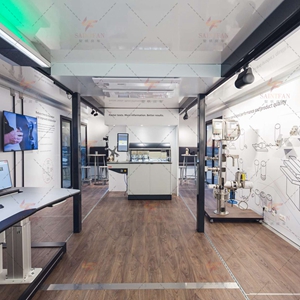
Having a dedicated workspace in your garden can be a game-changer for your productivity and overall work experience. The Garden Office Pod by WAH Solutions offers numerous benefits that can transform your work environment into a haven of focus and creativity. First and foremost, having a separate workspace away from the distractions and noise of your home can greatly enhance your concentration. When you step into your garden office pod, you enter a zone specifically designed for work. This separation from the rest of your living space allows you to mentally switch gears and fully immerse yourself in your tasks, free from interruptions. Additionally, the spaciousness of the Garden Office Pod provides ample room for you to set up your ideal work environment. Whether you prefer a minimalist setup or require space for multiple monitors and equipment, this pod can accommodate your needs. The natural light that floods the space creates an inviting and energizing atmosphere, boosting your mood and motivation. One of the greatest advantages of having a dedicated workspace in your garden is the opportunity to enjoy the beauty of nature while you work. The Garden Office Pod seamlessly integrates with the outdoor surroundings, offering stunning views and a tranquil environment. This connection to nature has been proven to reduce stress levels, increase focus, and enhance overall well-being, allowing you to work in a more relaxed and inspired state. Furthermore, the versatility of the Garden Office Pod allows you to customize it according to your specific requirements. Whether you need a private office, a creative studio, or a peaceful retreat for remote work, this pod can be tailored to suit your needs. The flexibility it offers ensures that you have a space that truly supports and enhances your work, regardless of your profession or industry. In conclusion, having a dedicated workspace in your garden provides a multitude of benefits that can transform your work environment for the better. The Garden Office Pod by WAH Solutions offers a spacious and customizable solution that allows you to enjoy the advantages of a separate workspace while being connected to nature. Embrace this opportunity to optimize your productivity, focus, and overall well-being, and experience the positive impact it can have on your work-life balance.