Understand the Key Differences to Find Better Acoustic Solutions
When people start looking for ways to reduce noise, a common question keeps recurring:
Are acoustic panels and soundproofing the same?
In short, the answer is no—but a complete explanation is more valuable. Understanding the difference between acoustic treatments and soundproofing can help you choose the right solution, avoid unrealistic expectations, and allocate your budget wisely.
In this article, we will explain the differences between the two in a clear and easy-to-understand way, combined with expert insights from experienced acoustic panel manufacturers.
What are Acoustic Panels?
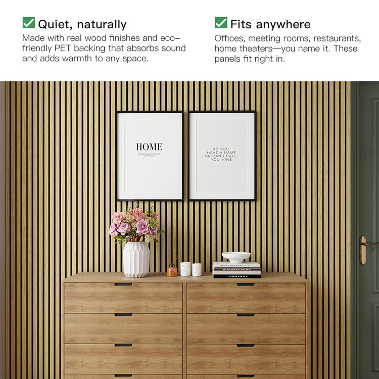
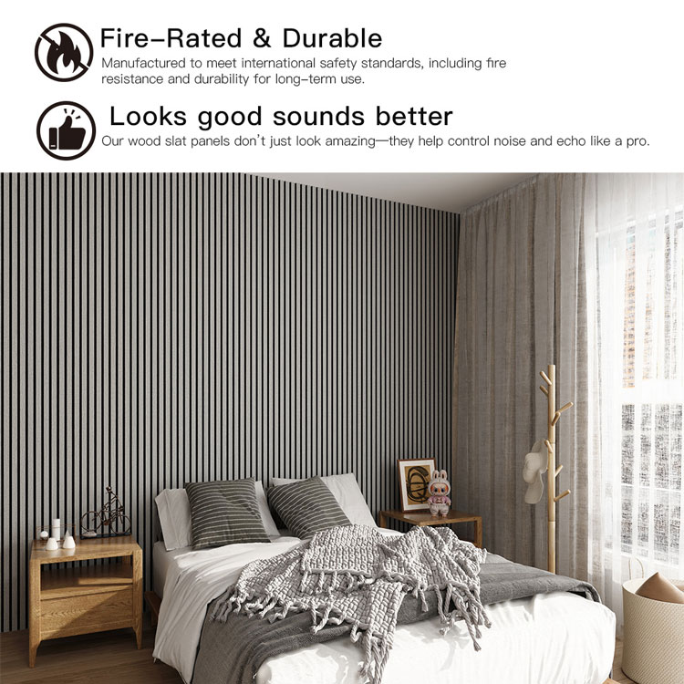
Acoustic panels are designed to improve the sound quality of a room by absorbing sound waves. They primarily target mid-to-high frequency reflections, reducing echoes, reverberation, and noise buildup.
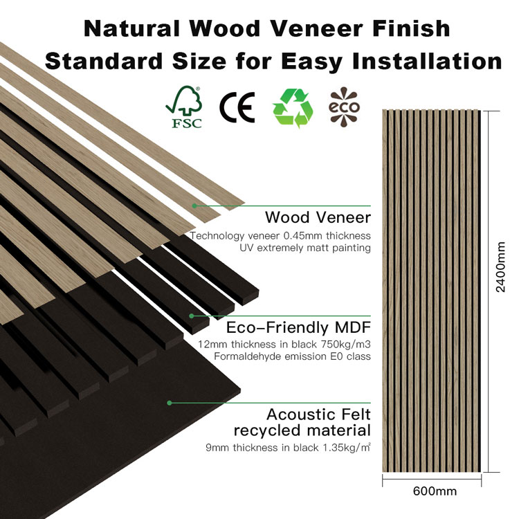
Most acoustic panels are made of sound-absorbing materials such as:
Acoustic felt or PET fiber
High-density MDF board with backing
Mineral wool or foam core
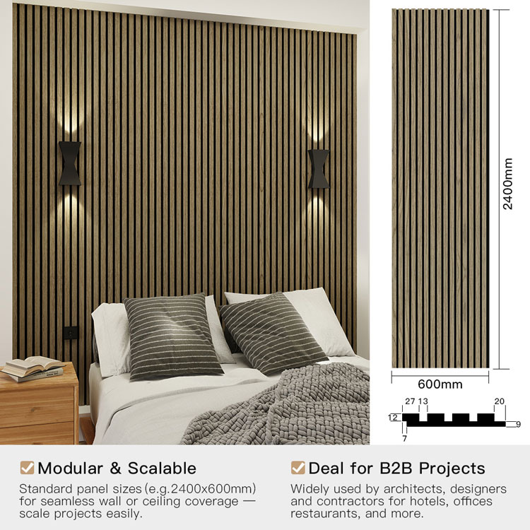
Common forms of acoustic panels include wood strip acoustic wall panels, fabric-covered acoustic panels, and decorative acoustic systems.
Advantages of sound-absorbing panels:
Reduces echo and reverberation
Improves speech clarity
Enhances music and audio quality
Creates a more comfortable acoustic environment
What is soundproofing?
Soundproofing focuses on preventing sound from entering or leaving a room.
True soundproofing requires structural solutions to address the following issues:
Sound propagation through walls, floors, and ceilings
Vibration propagation within the building structure
Air gaps around doors, windows, and electrical outlets
Common soundproofing methods include:
Increasing mass (e.g., adding drywall, high-density sound insulation materials)
Structural vibration isolation (e.g., double-wall construction, flexible joists)
Sealing gaps with acoustic sealants
Structural treatment of floors and ceilings
Sound Absorbers vs. Sound Insulation: Key Differences
Aspects: Sound Absorbers, Sound Insulation
Main Uses: Improves indoor acoustics, Blocks sound propagation
Affects: Reflected sound within the room, Sound passing through the building
Installation Methods: Surface mounting, Structural modification
Cost: Medium, High
Typical Applications: Studios, offices, residences, apartments, shared walls, noisy environments
👉 Sound absorbers cannot replace sound insulation, but they are often the first and most practical step.
Why Sound Absorbers are Often Misunderstood as Sound Insulation Materials
Many people find their rooms quieter after installing sound absorbers. This leads them to mistakenly believe they have achieved soundproofing.
However, the reality is:
Echoes and reflections are reduced.
Sound energy is contained within the room.
Noise sounds less harsh and more comfortable.
However, external noise (neighbors, traffic, footsteps) can still be heard because the sound-absorbing panels are not heavy enough to block sound propagation.
How Sound-Absorbing Panels and Soundproofing Materials Can Work Better Together
In professional projects, sound-absorbing panels are often used in conjunction with soundproofing measures.
For example:
Soundproofing the wall structure to reduce noise transmission.
Installing wood strip sound-absorbing panels to optimize sound clarity and aesthetics.
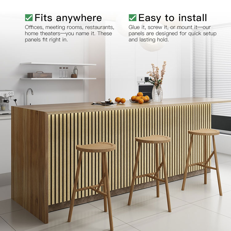
This combination is widely used in:
Recording studios
Home theaters
Office meeting rooms
Hotel and commercial interior spaces
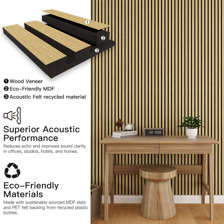
Why Wood Strip Sound-Absorbing Panels Are a Wise Choice
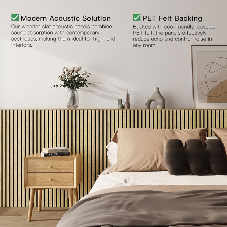
Wood strip wall panels offer unique advantages: they perfectly combine functional sound absorption with modern interior design.
The strip-shaped medium-density fiberboard (MDF) surface helps diffuse sound, while the sound-absorbing felt backing absorbs reflected sound—making it ideal for both performance and aesthetics. Manufacturing Quality is More Important Than You Think
Not all sound-absorbing panels perform the same. Factors such as the density of the medium-density fiberboard (MDF), the thickness of the felt layer, cutting precision, and bonding quality all directly affect sound absorption.
Why Global Customers Choose Our(leeyin) Acoustic Products
🏭 20,000 square meters of modern production facilities
📦 Strong capacity for handling bulk and project orders
🌍 One of China's leading exporters of wood strip wall panels
📐 Strict adherence to international quality management standards
🎯 Stable performance, consistent dimensions, and exquisite craftsmanship
Our products are trusted by distributors, designers, and contractors worldwide.
So, are sound-absorbing panels and sound-insulating panels the same?
No—but they are both crucial.
Acoustic panels:
Improve indoor sound propagation
Enhance comfort, clarity, and usability
Sound insulation panels:
Block noise propagation between spaces
Requires a structural solution
Acoustic panels offer the highest return on investment for most residential and commercial interior spaces, especially when sourced from specialized manufacturers.